


Project
Solar Cold Storage System
- Vapour Absorption Refrigeration System (VARS)
- Bubble visualization in a bubble absorber and generator with swirl entry.
- To evaluate the performance of the absorber generator in VARS with swirl entry of strong solution.
- Development of compact VARS cold storage.
- Vapour Jet Refrigeration System (VJRS)
- To study the performance characteristics of ejector under swirl generator.
- To visualize the flow field in the ejector.
- Development of compact ejector cold storage system.
Solar Desalination system (Phase – I)
Heat and mass transfer enhancement studies using thermal spray coated, metal foamed surfaces in multi-effect solar sea water desalination system
(a) Using Image processing technique :
The falling fluid film over the tube can be recorded along the axis of the horizontal tube at any one end, as shown in Figure 1. A high speed camera to be used to record the film over the horizontal tube. The recorded video is broken down into frames. By image processing software like ImageJ, thereby, we can measure the film thickness. The flow diagram for film thickness measurement using image processing is shown in Figure 2. The measurement of film thickness using an image processing technique can be performed at operating conditions of the desalination system. Simultaneous measurement of temperature and film thickness at the same location using high-speed video camera and infrared thermometry will give an insight to the relation between fluctuation of water film and the heat transfer mass transfer characteristics.
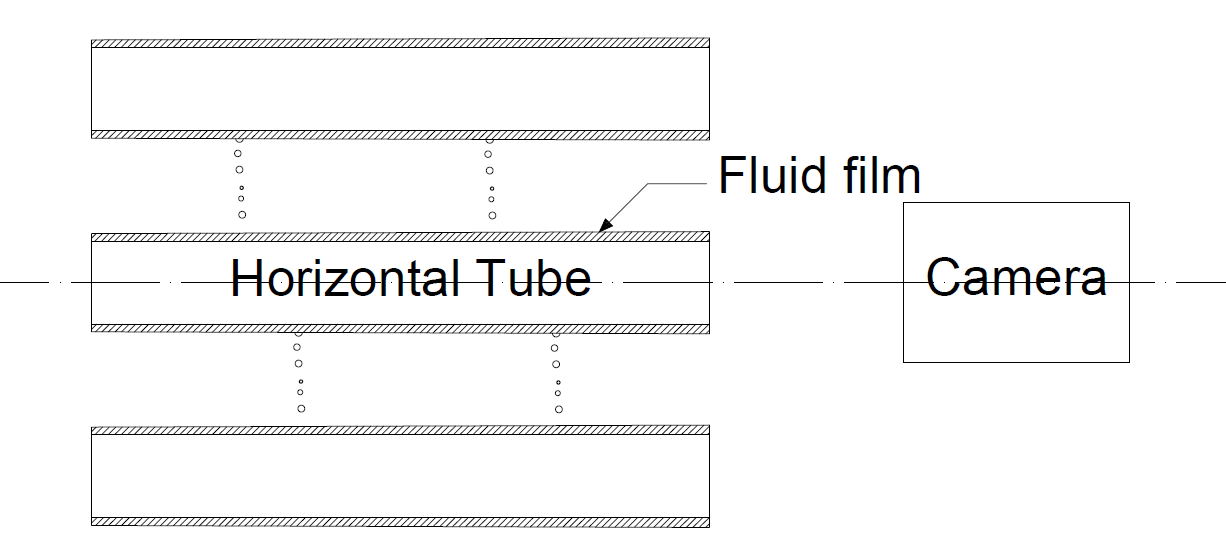
Schematic view of film thickness measurement
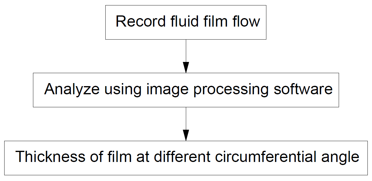
Flow diagram for film thickness measurement
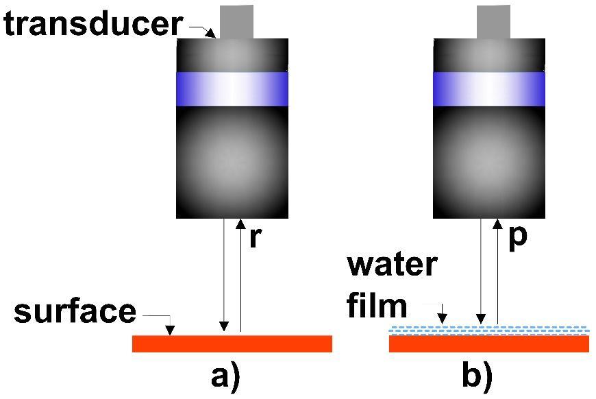
(b) Using ultrasonic transducers :
Ultrasonic transducers were externally triggered and operated in pulse-echo mode, where the transducer acts as the emitter as well as the receiver. The round-trip travel time of ultrasonic wave gives the measure of film thickness. Figure 3 shows the schematic of air-coupled ultrasonic transducers when operated in pulse echo mode. Air coupled type ultrasonic transducer (ACUT) was kept normal to the measuring surface. Ultrasonic signal from the transducer, in the ACUT technique, completely reflects from the air-water interface. The reflected signals are received by the sensor and the time difference between the reflected signals is the measure of the water film thickness. Film thickness measurement using ACUT requires a reference signal. For measuring the water film thickness over inclined plate, reflected signal from the plate in the absence of flow was considered as the reference signal as shown in Figure 3. Shift in the signal peak due to the flow was determined by performing a cross-correlation operation between the reflected signal from liquid-air interface and the reference signal. The position of the absolute maximum of the cross correlation function was found out and the instantaneous liquid film thickness value is obtained.
Schematic for measurement of a) reference signal b) flow signal.
(c) Using laser interferometry :
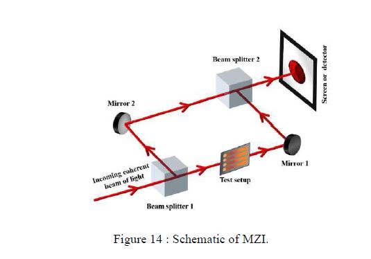
The Mach-Zehnder interferometer (MZI) is a popular configuration for studies in heat and mass transfer in fluids. Schematic of MZI is shown in Figure 4. The optical components namely beam splitters and mirrors are inclined exactly at an angle of 45° with respect to the beam direction.
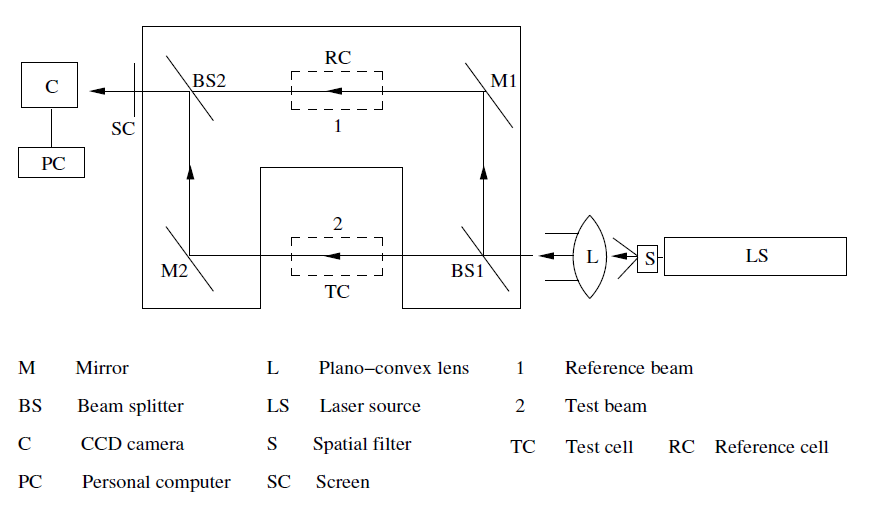
Schematic of a Mach- Zehnder Interferometer
The first beam splitter splits the incoming collimated beam into two equal parts, namely the transmitted and reflected beams. The transmitted beam is the test beam and the reflected beam is the reference beam. The test beam passes through the test region, is reflected by the mirror, and recombines with the reference beam on the plane of the second beam splitter. The reference beam undergoes a reflection at the second mirror and passes through the reference medium and superposes with the test beam at the second beam splitter. On superposition, the two beams produce an interference pattern. This pattern contains information about the variation of refractive index in the test region. The Mach-Zehnder interferometer can be operated in two modes, namely infinite fringe setting and wedge fringe setting. In the former, the test and reference beams are set to have identical geometrical path lengths, and the fringes form due to refractive index changes alone. Since each line is a line of constant phase, it is also a line of constant refractive index. The fringe thickness is an inverse measure of the local refractive index gradient, being smaller when the gradients are high. This setting is used for high-accuracy refractive index measurements. In the wedge fringe setting, the mirrors and beam splitters are deliberately misaligned to produce an initial fringe pattern of straight lines.
(d) Scale formation studies:
The modified heat exchanger tube will be subjected to continuous operation with seawater. The increase in tube weight will be monitored at intervals to estimate the scale formation. After reaching a total operating time of 200 hrs., the scale formed on the tube surface is scrapped out to carry out mineralogy studies. Scale formation rate of modified tube surface will be compared with bare tube. As the modified tube offers higher heat transfer area, a higher scale formation on the tube surface is expected
Solar Desalination system (Phase – II)
Domestic compact solar desalination system
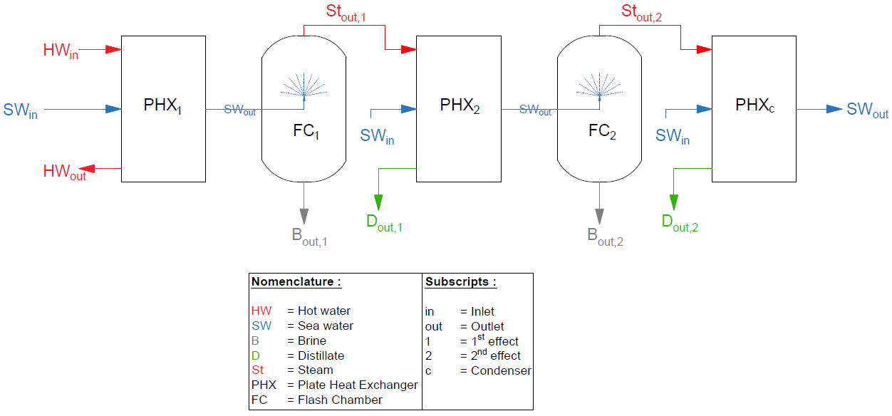
Figure 5 shows the desalination process using plate type heat exchanger. In first effect plate heat exchanger (PHX1), seawater or brackish water temperature can be raised (say 5 – 6oC) from the inlet seawater temperature by gaining heat from the heating source (say solar hot water heater). The heated seawater from PHX1 is flashed at corresponding saturation pressure in the flash chamber (FC1). The flashed steam is carried to the next effect, and the process repeats until it reaches the condenser. In plate heat exchanger condenser (PHXc), the produced steam from the last effect is condensed. The remaining seawater from the flash chamber is known as brine (B) and is rejected.
Schematic diagram of a domestic compact desalination system.
Development of Solar Vapour Absorption Refrigeration Cold Storage (Phase – I)
In bubble type absorber, the refrigerant vapour coming from the evaporator will be bubbled through the weak solution by using a vapour distributor, i.e. nozzle as shown in f Figure 6. Refrigerant vapour bubble will grow from the nozzle, detaches and rises upwards through a solution; as a result, the interfacial area between vapour and solution will be increased. Hence, good mixing is possible between vapour and weak solution. Also, bubble absorber results in good wettability characteristics because the vapour bubble always surrounded by the weak solution until its disappearance.
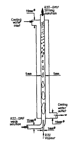
Bubble absorber (Sujatha et al., 1999)
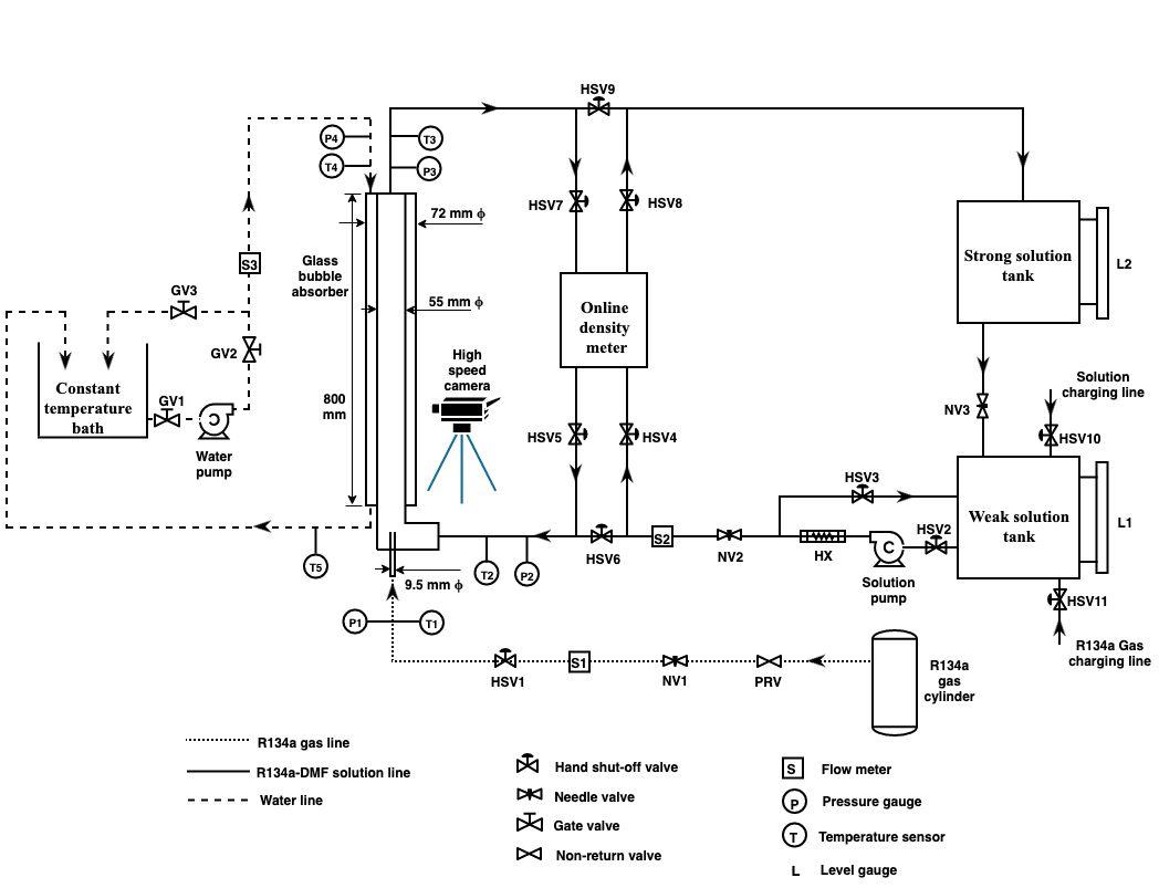
Schematic diagram for bubble visualization studies.
Schematic diagram for bubble visualization studies.
The same experiments will be repeated on the compact bubble absorber for heat and mass transfer studies with swirl entry. From the experimental results of a tubular and compact absorber, a comparative study will be carried out to find the best performing absorber with swirl entry.
(b) Generator:
Generator is considered as one of the vital components in the vapour absorption refrigeration system (VARS). The function of a generator in a VARS is to generate pure refrigerant vapour from the refrigeration-absorbent strong solution when low-grade heat energy is supplied from an external (waste heat or renewable energy) sources. As a result of the desorption process, strong solution is converted into a weak solution and refrigerant vapour. The vapour from the mixture is separated in the gas separator and is sent to condenser and evaporator to produce refrigeration effect in the cycle.
A good generator in the VARS system is required to give a maximum possible difference in concentration between the solutions at the entry and exit of the generator, with the available temperature of waste heat/solar energy source. An efficient generator requires only lesser amount of heat, to generate a unit mass of refrigerant vapour. Consequently, for the same amount of refrigeration effect produced, heat supplied to the system using an efficient generator is reduced. Hence, the generator is one of the crucial components of the VARS system, whose efficiency of refrigerant vapour desorption influences to enhance the performance of the system significantly.
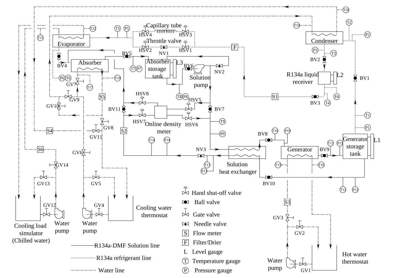
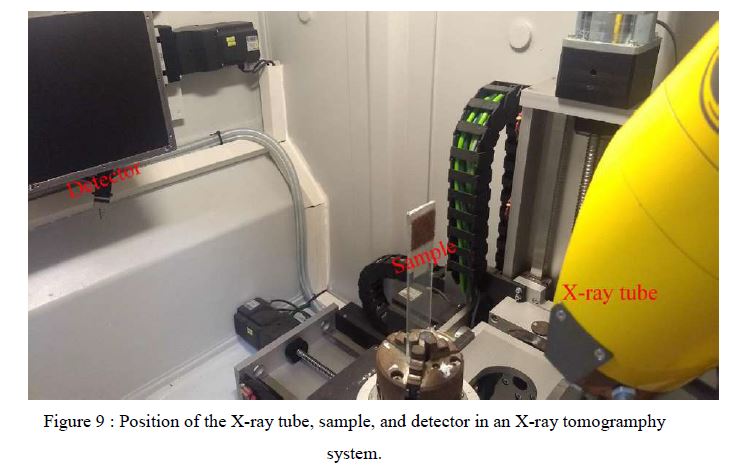
Experiments will be carried out on the tubular generator with swirl entry to study the heat and mass transfer characteristics. Swirl generator will help in increasing the residence time of the strong solution in the generator; hence, there will be large heat flux can be taken by the strong solution and generates more refrigerant vapour from it. Also, the effect of operational parameters like, solution pressure, temperature, initial solution concentration, and heat flux supplied on the performance of the tubular generator. The schematic diagram for this experimental study is shown in Figure 9. The same experiments will be carried out on the compact generator, and comparative studies will be carried out to identify the efficient generator. A numerical model will be developed to estimate the local heat and mass transfer rates in a generator of the vapour absorption refrigeration system. Flow visualisation studies will be carried out on the generator to understand the generation phenomenon of R134a vapour from R134a-DMF solution.
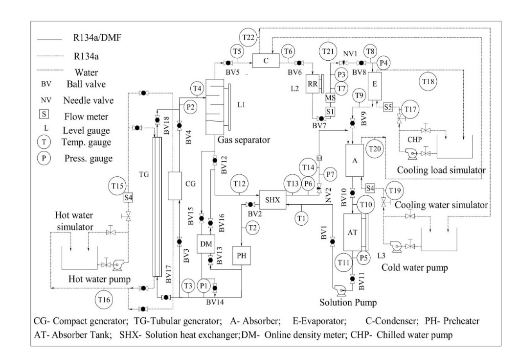
Experimental schematic diagram of VARS with tubular and compact generators.
Solar operated cold storage system.
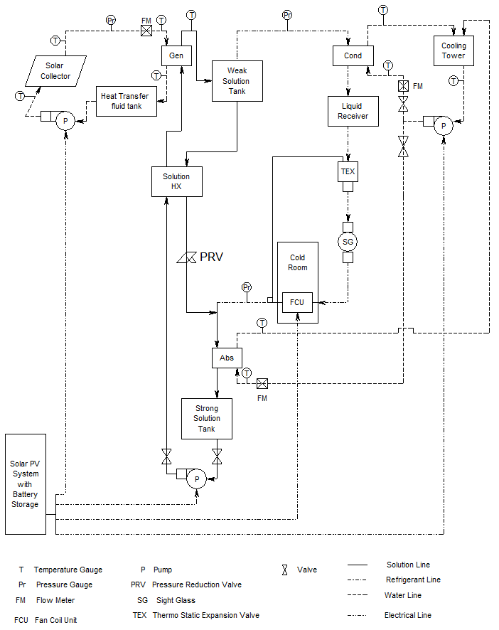
Integration of solar PV power plant system, Solar thermal system, and Compact VARS makes the solar operated cold storage system. The line diagram of integration of subsystems shown in figure 10.
Once the erection of the plant is completed successfully, charging of the system will be done with the help triple vacuum technique. Detailed heat and mass transfer studies will be carried out on the water-cooled VARS cold storage with instrumentation. Effect of parameters viz., gas flow rate, solution flow rate, initial solution concentration, solution pressure, solution temperature, cooling water flow rate and hot water flow rate on absorber and generator performance. Studies will be carried out to understand the effect of component temperatures viz., generator, absorber, condenser, and evaporator on performance parameters like circulation ratio and coefficient of performance, and to study the effect of circulation ratio on system performance. From these results, the system performance characteristics will be understood and help to fabricate a compacted system. A compact cold storage will be developed without instrumentation. This compacted storage system can be taken to anywhere and install at any place where the solar energy is abundantly available.
Development of Compact Solar Vapour Jet Refrigeration System (Phase – I)
Initially, the ejector dimensions will find out by doing 1D analysis. Once the ejector dimensions were finalized the shape of the ejector will be decided by the optimization studies. It is to be noted that in circular cross-section ejectors, optical access to the ejector becomes difficult due to curvature of the wall. Consequently, the main focus of this work is to design a non-circular cross-section ejector for accurate visualization and quantification without optical distortion present in the circular ejector. Also, Studies in the past have been focused on large cross-section rectangular ejectors where the boundary layer causes the least effect on the flow field. Hence, a small and compact ejector will be modelled in this study.
Once the shape and design of the ejector are finalized, the performance of ejector with different working fluids (air, water, environment-friendly refrigerant) will be analyzed by different flow visualization techniques namely, PIV and lase interferometry methods. The schematic diagram of flow visualization technique is shown in Fig. 11. The ejector test rig comprises of working fluid reservoir for supplying at a maximum gauge pressure of about 10 bar, transparent ejector and ball valve arrangement for controlling the flow, measuring instruments like rotameter, orifice, pressure transducers and data logger for continuous monitoring of pressures variation. The static pressure will be approximately equal to the total pressure, as the inlet and outlet velocities are very low compared to the supersonic condition of the primary nozzle. The secondary mass flow rates are determined using orifice plate equipped with an inclined U-tube manometer using water as monomeric liquid. The detailed experiments will be carried out, and parametric analysis will be carried out. A numerical model will be developed to simulate the ejector, and these results will be compared with the experimental and visualization studies results.
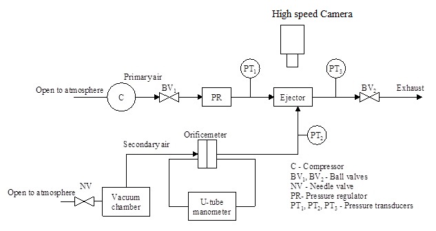
The schematic diagram of flow visualization studies.
Numerical studies will be carried out on various types of swirl geometries with the help of Ansys FLUENT 18.1. From the numerical results, the optimum swirler geometry will be identified. Once, the swirler geometry is finalized, visualization studies will be carried out on a swirl entry ejector in the primary nozzle working with different working fluids with the help of a high-speed camera. Due to the swirler in the primary nozzle stream, the working fluid coming from the diffuser section of the primary nozzle undergoes a swirl path, which results in higher entrainment of the secondary stream. Hence, there will be improved ER, which results in good performance characteristics of the ejector, which helps to improve the overall system performance. Experiments will be carried out on swirl entry ejector to estimate the performance parameters of the ejector. Then, the parametric analysis will be carried out. Finally, numerical analysis of swirl entry ejector will be carried out, and comparison of numerical results with experimental and visualization results will be carried out.
Development of Compact Solar Vapour Jet Refrigeration System (Phase – II)
From phase I results, the solar VJRS will be fabricated with the optimum configuration of ejector. In this phase, the solar energy is utilized to supply the heat flux in the generator, which is abundantly and freely available in India. Integration of the solar PV, solar thermal and VJRS the solar operated vapour jet refrigeration system.
Once the erection of the plant is completed successfully, charging of the system will be done with the help triple vacuum technique. Detailed heat transfer studies will be carried out on the water-cooled VJRS with instrumentation. Parametric analysis will be carried out to study the ejector performance characteristics. Studies will be carried out to understand the effect of component temperatures viz., generator, condenser, and evaporator on performance parameters ER and compression ratio. From these results, the system performance characteristics will be understood and help to fabricate a compacted system. A compact VJRS will be developed without instrumentation. This compacted VJRS system can be taken to anywhere and install at any place where the solar energy is abundantly available.
The value of a solar thermal plant ultimately is judged based on its economy. In this work, the commercial quantities are evaluated to find the economy of the installed plant. As is evident by now, solar thermal systems are characterized by high initial costs. However, they bring long term benefits in the form of lower annual operating costs. An economic evaluation of solar plant should consider both these aspects. Economic analyses will carry out the fabricated system, to find out the annular solar savings, the payback period of the system, and eco-friendly evaluation (amount of CO2 reduction).Expected deliverables of the research
- High impact factor journal publications.
- Manpower development (PhD and MS scholars).
- International collaboration.
- Industrial collaborations.
- International exchange program.
- International conferences.
Current status
Solar Desalination system
Purchase of equipment Equipment Name Current Statues High-speed camera Process of releasing Purchase Order Infra-Red Camera Process of releasing Purchase Order Ultrasonic sensor Under processing Pulser / Receiver Purchase Order released DAQ card Purchase Order released Flow meters (Ultrasonic type) Process of releasing Purchase Order Pressure sensors with transmitters and indicators Under processing Vacuum sensors with transmitters and indicators Under processing Temperature sensors with transmitters and indicators Under processing Data logger with Multiplexer Modules Order released and delivered to RAC Lab Mirror, beam splitter and accessories Under processing
Solar Cold Storage
Purchase of equipment Equipment Name Current Statues Hermetic solution pump Under processing Online density meter (Multi component liquid solution) Process of releasing Purchase Order Mass flow controller Under processing Differential Manometer Purchase Order released Camera endoscope, Laser endoscope arms for transmitting laser sheet Under processing
1.1. Using Image processing technique
Objectives:
- To develop a falling film thickness measurement technique over a horizontal tube (plain tube and foam tube) using an image processing technique in conjection with high speed camera.
- To study film formation over the horizontal tube (plain tube and foam tube) along longitudinal length.
- To study the temperature profile of falling film over horizontal tube (plain tube and foam tube).
- To compare this new measuring technique of film thickness with available techniques in the literature.
Summary of Work Done:
- The equipments required for falling film measurement studies using the image processing technique has been purchased. The few equipment has reached the Refrigeration and Air Conditioning (RAC) Laboratory, Department of Mechanical Engineering IIT Madras.
- The list of equipment that has been ordered and its status are listed below:
| S.No | Equipment details | Status |
|---|---|---|
| 1. | High Speed Camera | 1.Reached RAC Lab and demonstration completed. 2. Figure 1 – Photograph of High speed Camera and non-flickering led light. |
| 2. | High Speed Infra-Red Camera | 1.Yet to reach RAC Lab. |
| 3. | Data Acquisition system | 1.Reached RAC Lab and demonstration completed. 2.Figure 2 – Photograph of Data Acquisition system. |
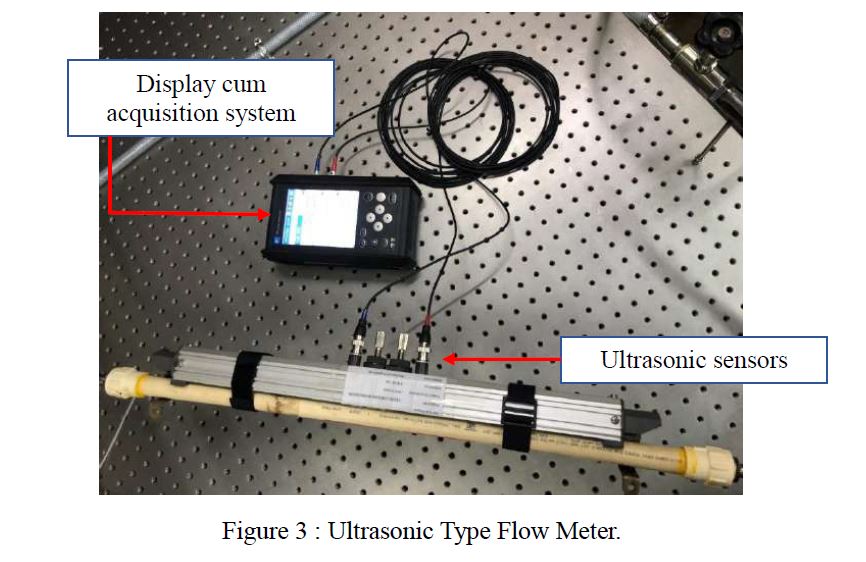
| 4. | Ultrasonic Type Flow Meter | 1. Reached RAC Lab and demonstration completed. 2 Figure 3 – Photograph of Ultrasonic Type Flow Meter. |
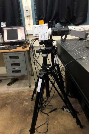
(a) High speed camera with tripod.
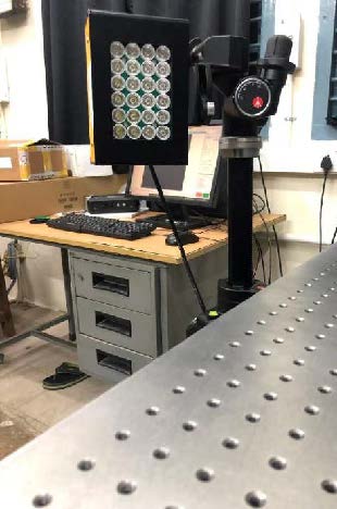
(b) Non-flickering led light with tripod
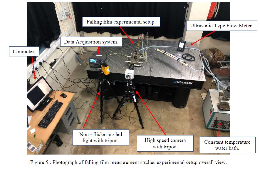
Figure 1 : Photograph of High speed Camera and non-flickering led light.
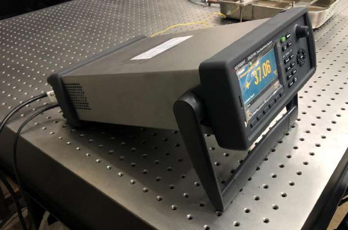
Figure 2 : Photograph of Data Acquisition system.
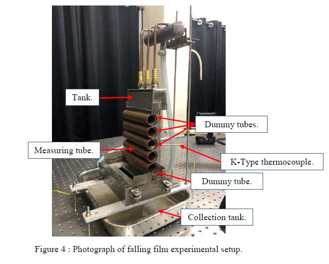
- The experimental setup for falling film measurement technique studies has been fabricated and installed at RAC Laboratory, Department of Mechanical Engineering IIT Madras. The photograph of the falling film experimental setup installed in the RAC lab is shown in figure 4.
- Figure 5 shows the overall view of falling film measurement studies experimental setup at RAC Laboratory, Department of Mechanical Engineering IIT Madras.
- Initial trials have been started using high speed camera to measure the falling film thickness over the horizontal tube (plain tube).
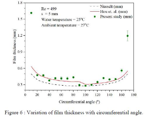
- Drinking water was used for initial trials with a plain tube of inner diameter 25.4 mm. Water temperature was constantly maintained at 25oC using a constant water bath, and ambient temperature was maintained at 27oC.
- The flow rate of working fluid was maintained at 1 lpm, which corresponds to Reynolds number of 499.
Results
Variation of film thickness with respect to circumferential angle was studied for plain tube and it is as shown in Figure 6.
Future Plans
- Detail experimental studies using high speed camera to measure the falling film thickness over the horizontal tube (plain tube and foam tube) will be carried.
- Detail temperature profile studies of falling film over horizontal tube (plain tube and foam tube) will be carried out after high speed infra red camera reaches RAC lab.
- The results will be compared with the available techniques in the literature.
1.2. Using ultrasonic transducer
Objectives – Part A:
- To develop a falling film thickness measurement technique over a horizontal tube (plain tube, thermal spray-coated tube, and metal foam wrapped tube) using a non-contact ultrasonic transducer.
- To study the formation of film thickness over the horizontal tube at longitudinal length.
- To compare the new measuring technique of film thickness with researches attempted by various techniques.
Objectives – Part B:
- To find effective thermal conductivity of copper metal foam,
- Using X-ray computed microtomography images to find hollow portions of the ligament and the node.
- To study the effect of hollowness and how it affects the effective thermal conductivity of metal foam.
- To compare the effective thermal conductivity obtained with the analytical and empirical models available in the literature.
Summary of Work Done:
- Background study of falling film over Horizontal tube is done.
- Design of falling film thickness measuring technique is completed.
- Fabrication of experiment setup and installation is done.
- Background study of Metal foam is finished.
- Sample study of metal foam under X-ray computed microtomography is done.
- The equipment required for falling film measurement studies using ultrasonic transducer has been purchased. The few equipments has reached except transducers the Refrigeration and Air Conditioning (RAC) Laboratory, Department of Mechanical Engineering IIT Madras.
- The list of equipment that has been ordered and its status are listed below:
| Si. No. | Equipment details | Status |
|---|---|---|
| 1. | Ultrasonic transducer | 1.Purchase order released. |
| 2. | NI DAQ system | 1. Reached RAC Lab and demonstration completed. 2. Figure 7 - Photograph of NI DAQ system. |
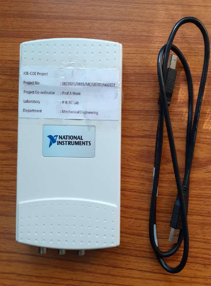
Figure 7 : Photograph of NI DAQ system.
Experimental Setup:
Figure 8 shows the experimental setup developed for the film thickness measurement using ultrasonic transducer
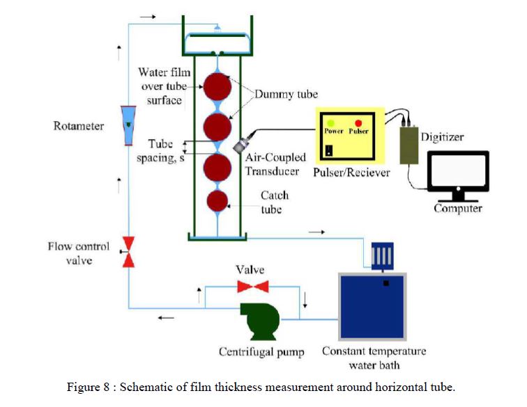
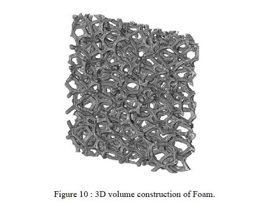
Figure 9 and Figure 10 show few images of metal foam.
Results
As shown in figure 11, falling film thickness was found to increase with falling film Reynolds number, for both plain and MFL tubes. A slight decrease in film thickness was observed for high flow rates in plain tube, possibly due to water splashing. An average deviation of 7.5% and 7.3% was observed for falling film over plain and MFL tubes, respectively.
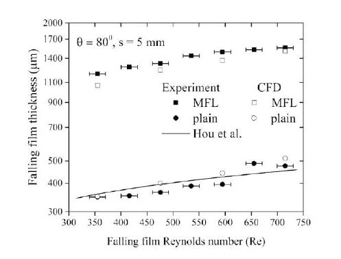
Figure 11 : Variation in falling film thickness with falling film Reynolds number, for flow over MFL and plain tube.
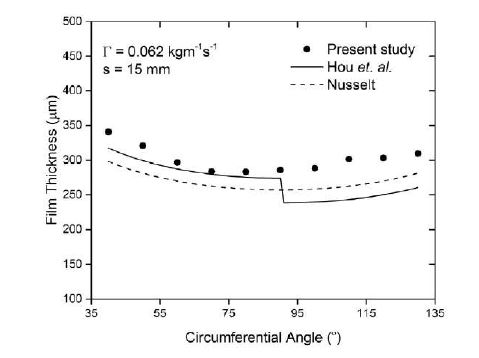
Figure 12 : Film thickness measurement around the tube.
As can be seen in Figure 12, Film thickness measured using the present study is higher than that obtained from the Nusselt expression by 8 - 15% and average deviation of 12%. This deviation may be due to the assumptions in Nusselt analysis, which considered a sheet flow between the tubes. Also, the effects of the tube spacing and the tube diameter were not considered in the Nusselt’s study.
Visible outcomes:
- A. Jayakumar and A. Mani, Image-based method for evaluation of effective thermal conductivity of metal foam with hollow ligaments, International Journal of Heat and Mass Transfer, 2021;164:120490.
- J. Arjun, A. Mani, Experimental and Numerical Study of Hydrodynamic and Heat Transfer Characteristics of Falling Film Over Metal Foam Layered Horizontal Tube, J. Heat Transfer. (2021).
1.3. Using laser interferometry
Objectives:
- To develop a falling thin film measurement technique over a horizontal tube using laser interferometry technique.
- To calculate the falling film interface temperature and a shadowgraph approach to estimate film thickness simultaneously.
- Dynamic film thickness studies can also be incorporated for the entry region and exit region of the flow.
- To compare the new measuring technique of film thin with researches attempted by various other techniques.
Summary of Work Done:
Experimental Setup:
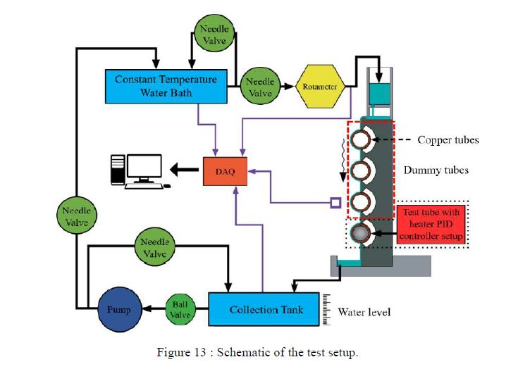
A horizontal tube falling film evaporator setup consisting of three dummy tubes, a test tube, and a feed distributor system was fabricated. The schematic for the same is shown in figure 13. The fluid flow setup consists of a water bath, rotameter, a test setup, a collection tank, and a recirculating pump. All water flow connections were made using PEX tubes, which can handle high-temperature water flow up to 200℃. The feed distributor system was fabricated using the material SS316 with a calibrated top tank of dimension 180×25×35 mm3. The feed distributor tank was divided into two parts using a partition wall. The partition wall was drilled with 18 equidistant holes of diameter 2.0 mm through which the water falls to the lower part from the upper part of the feed distributor tank. The feed inlet water then proceeds towards a semi-circular section of diameter 5.0 mm as depicted in figure 13. The semi-circular section’s use was to damp the disturbances in the stream to get a thin and uniform flow of water over the effective length of the evaporator. The test and dummy tubes were fabricated using copper tubes of outer diameter 15.9 mm. The purpose of using dummy tubes was to obtain a stabilized and evenly spread flow with minimum edge effects. The fourth tube is equipped with heater PID controller setup, so that wall temperature of the tube can be increased as required.
An in-house Mach Zehnder Interferometer (MZI) system was designed and fabricated for measuring the falling film thickness and interface temperature. The schematic for the ray diagram for the same is shown in Figure 14. The required beam size was achieved by using the laser source along with a collimating arrangement. As evident from it, Beam Splitter 1 (BS1), Mirror 1 (M1), Mirror 2 (M2) and Beam Splitter 2 (BS2) are all placed at an angle of 45º with respect to the laser beam direction. The function of BS1 is to split the incoming laser beam into two, i.e., transmitted beam and reflected beam. Then the reflected beam transverses towards M1 and gets reflected towards BS2. Similarly, the transmitted beam gets reflected by M2 towards BS2, and both the rays superimposes and generates the interference patterns. They are grabbed using a CCD device for further analysis. In this work, the interferometer is operated in the infinite fringe mode where the two beams interfere to produce a fringe free field. The main advantage of using this mode is that the fringe generation is only accompanied by a thermal disturbance at the test setup. For the infinite fringe setting, a fringe is a line of constant phase, i.e., line of constant refractive index and constant density resulting in a constant temperature field (isotherm).
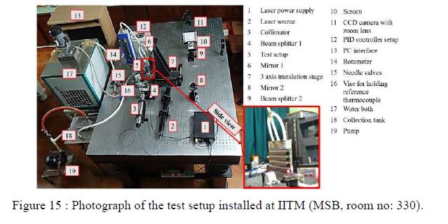
In this work, the test setup (horizontal tube with PID controller setup) is placed inside the field of view of MZI as shown in figure 14. The photograph of the entire test setup along with interferometer components are shown in figure 15. The entire test setup, along with the three-axis translation stage, is mounted on top of an active optical bench as shown in figure 15.
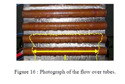
Some additional images are provided (Figures. 16 - 22) to get an insight into the analysis and output.
Results:
Variation of heat transfer coefficient and film thickness with respect to variation of circumferential angle is studied as shown in following Figures (Figure 17 – Figure 20).
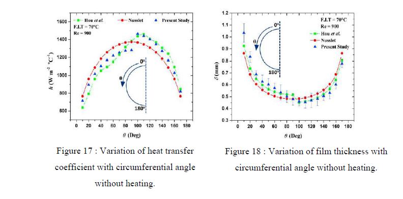
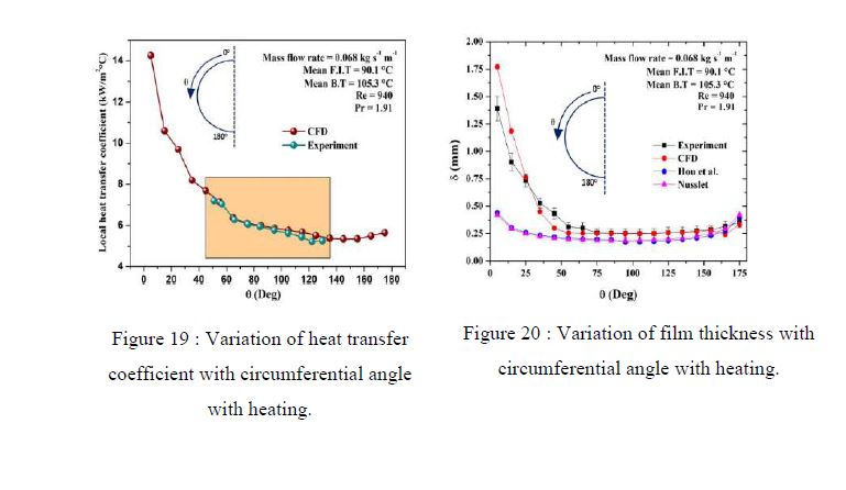
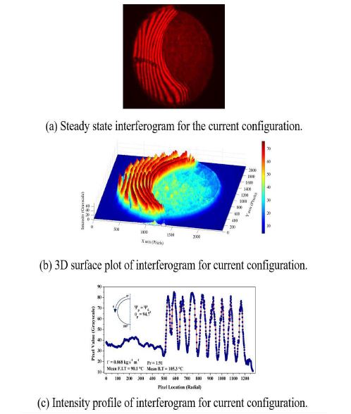
Figure 21 : Sample set of images used for film interface temperature calculation.
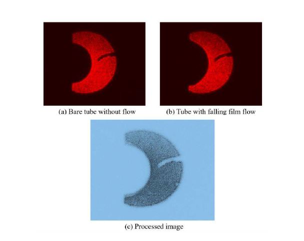
Figure 22 : Sample set of images used for film thickness calculation.
Conclusions
In this project, an optical shadow method (non-intrusive) was used to evaluate the falling film thickness around the circumference of a horizontal tube evaporator and interferometric technique was established to determine the local heat transfer coefficient. The novel method designed on the grounds of MZI was able to capture the behaviour of falling film thickness and falling film interface temperature simultaneously. Qualitative as well as the quantitative analysis was accomplished with an unprecedented circumferential angle of span.
Visible outcomes
- A.K. Maliackal, A.R. Ganesan, A. Mani, Interferometric analysis of flow around a horizontal tube falling film evaporator for MED systems, Int. J. Therm. Sci. 161 (2021)
- A.K. Maliackal, A.R. Ganesan, A. Mani, A novel interferometric method for simultaneous measurement of film thickness and film interface temperature for a horizontal tube falling film evaporator for MED systems, Int. J. Heat Mass Transf. 183 (2022) 122231. 17
- A.K. Maliackal, A.R. Ganesan, A. Mani, Measurement Of Film Thickness And Temperature On Horizontal Metal Spray Coated Tube Falling Film Evaporator Using Interferometric Technique, Int. J. Refrig. Air Condi., Purdue University Conf. (2021)
- {Won best paper award}
- A.K. Maliackal, A.R. Ganesan, A. Mani, Falling film thickness and interface temperature studies on a horizontal tube falling film evaporator with enhanced tube surfaces for MED systems emphasizing laser interferometry, [Submitted to Applied Thermal Engineering – Under review]
1.4. Absorbers Studies
Objectives:
- Numerical studies on bubble absorber to study bubble dynamics and to estimate the local heat and mass transfer rates.
- Bubble visualisation studies on a swirl entry tubular glass absorber with air and water.
- Bubble visualisation studies on tubular glass bubble absorber with swirl entry on the refrigerant (R134a) side to understand the absorption phenomenon.
- To conduct experimental studies on a copper tubular bubble absorber with swirl entry of refrigerant gas to find out the heat and mass transfer characteristics.
- To extend the experimental studies on compact bubble absorber with swirl entry on the gas side.
- To make comparative studies of tubular and compact bubble absorber.
Summary of Work Done:
- Numerical simulations were carried out, and the swirl generator model was finalised.
- 3D printing of the swirl generator was done whose material was compatible with air and water.
- An experimental setup for air bubble visualisation was fabricated to visualise bubble characteristics in still, counter current and concurrent water flow directions.
Swirl generator:
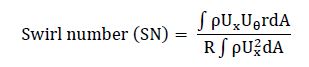
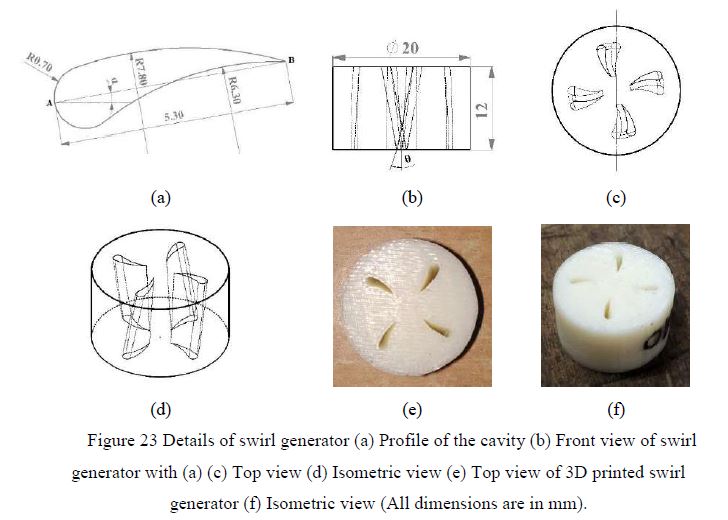
Swirling motion to air bubbles is imparted by a cavity-type swirl generator placed at the bottom of the absorber. To determine the optimum swirl generator (SG) geometry, different cavity profiles (near airfoil shape) are generated based on area constraint, as shown in figure 23a. Four different cavity profiles were generated for a given set of nozzles.By using different generated cavity profiles, various swirl generators are modelled with a different number of nozzles varying from one to five with equal spacing between them. Then, single-phase numerical simulations with the help of ANSYS Fluent 2019 R2 are carried out with air by placing the modelled swirl generator at the inlet of pipe under gravity conditions. The performance of the swirl generator is evaluated based on a non-dimensional number called swirl number, defined as the ratio of the axial flux of swirl momentum to the axial flux of axial momentum times the equivalent radius of the plain.
From the numerical results, the swirl generator of the cavity profile shown in figure 23a with four nozzles having 0o camber angle and 20o twist angle resulted in better performance characteristics than the other generated SG models. This swirl generator is fabricated with Fusion Deposition Modelling (FDM) type 3-dimensional (3D) printing method with Acrylonitrile Butadiene Styrene (ABS) material as depicted in figure 23e – figure 23f. Fabricated swirl generator is installed at the bottom of the absorber in the air stream with the help of a copper pipe.
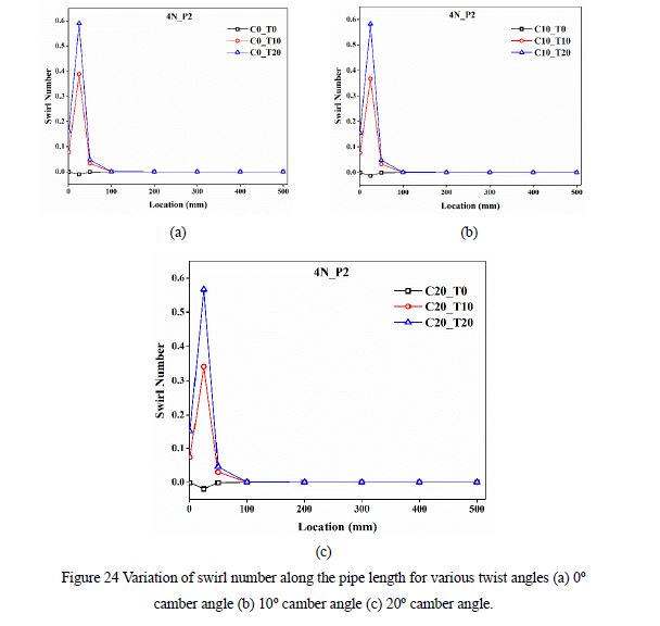
Cavity profile’s camber angle and twist angles varied from 0o to 20o to understand its effect on swirl intensity. Figure 24 shows the effect of twist angle on swirl intensity for the optimum swirl generator geometry as discussed above. The cavity profile’s twist angle helps the fluid divert along the twisted path. As a result, the fluid is undergoing a rotation or spiral motion. This fluid rotation helps to impart the tangential velocity to the flow. As twist angle increases, the magnitude of the tangential component of velocity increases due to this swirl number increasing, which is evident in figure 24. It can be observed that once the swirl number reaches the peak value, it is continuously decreasing towards the end of the pipe. Hence this type of swirl generator is classified under decaying type of swirl generator.
The cavity profile and its corresponding number of nozzles which results in maximum swirl number among the generated profiles for a given number of nozzles are shown in figure 25. It can be seen that the profile of 0o camber angle and 20o twist angle profile with four number of nozzles have shown promising results that other configurations. Hence, this configuration of the swirl generator is used to carry out further experimental studies.
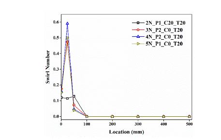
Figure 25 Comparison of various swirl generator models by the maximum swirl number.
Experimental setup
Figure 26 illustrates the schematic diagram of the experimental apparatus used to visualise air bubbles in water, including a glass bubble absorber, copper pipe with swirl generator, water tank, water pump, air compressor, valves and instrumentation. A glass tube of 85 mm ID, 89 mm OD and 1000 mm length is used as a bubble absorber in the present study. Air is being supplied from a two-stage reciprocating air compressor of storage tank capacity 220 liters through an air filter cum regulator and injected via swirl generator installed at the bottom of the absorber. Water is pumped from the water tank into the absorber by a multistage centrifugal water pump of 1.5 m3/hr capacity. The required water flow direction in the current study is maintained by altering the water inlet and outlet points. Air at the absorber outlet is escaped into the atmosphere, and water is sent back to the water tank for recirculation. A non-return valve is fixed in the air line to avoid the backflow of water in the absence of air supply to avoid the damage of the mass flow controller.
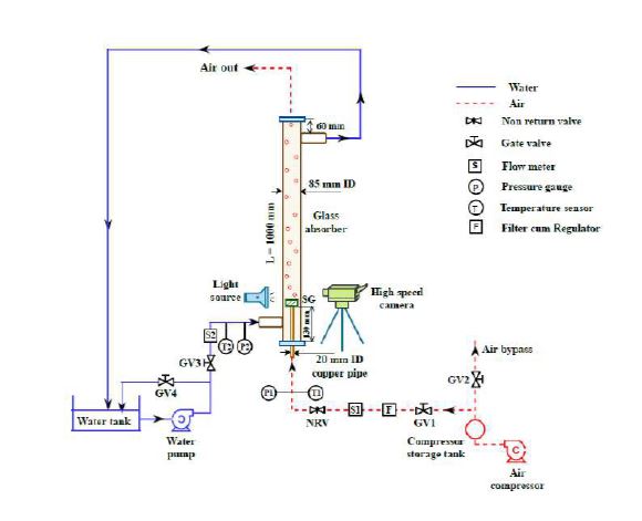
Figure 26 Schematic diagram of the experimental setup.
Experimental setup
Initially, the air compressor is switched on by keeping the compressor discharge valve closed. Once the pressure in the compressor storage tank reaches 5 bar, the discharge valve and bypass valves are opened to allow the air to flow to the absorber through the air filter cum regulator, mass flow controller and injected via swirl generator. Air pressure at the inlet of the absorber is always maintained between 1.2 to 1.5 bar with the help of filter cum regulator and by discharging some amount of air from a compressor storage tank into the atmosphere. The required air flow rate in the experiments is maintained with the help of a mass flow controller. Then, the centrifugal water pump is switched on to supply water. The pump is switched off after some time, and water remains still in the absorber. Water inlet pressure and temperature remain constant at 1.1 bar and room temperature, respectively. During this process, a high-speed camera with a spatial resolution of 4.8 μm/pixel and a video recorder is used to visualise the bubble behaviour. The absorber’s air is escaped into the atmosphere through the opening provided at the top of the absorber. This process is repeated for different gas flow rates, and visualisation studies are carried out. The process discussed above is conducted in still water in the absorber. The above experimentation is repeated with flowing water conditions, i.e. either co-current or countercurrent direction, by running the pump continuously. Water flow rate is measured by the glass rotameter, and desired water flow rate is achieved by bypassing the water with the help of a bypass valve.Water at the other end from the absorber is returned to the water tank to use the same water for further experimentation. The bubble photograph studies are carried out in water flowing situations with various water flow rates for a given air mass flow rate. Enough care has been taken in such a way that only air bubbles are generated from a single nozzle in each experiment to have only a bubbly flow to estimate the detachment bubble diameter. In current experiments, the air flow is always started first to avoid the backflow of water in the air line.Images of bubbles are taken alongside a reference object is placed inside the absorber. The air bubbles are captured from three sides of the bubble absorber with the help of the backlighting technique. It was noticed that the bubbles in the remaining two directions are identical to those seen in front of the bubble absorber. These images are uploaded in ImageJ 1.49 software, and the properties corresponding to bubbles are calculated by writing different macros. Figure 27 shows the schematic of the image processing procedure and diameter determination.
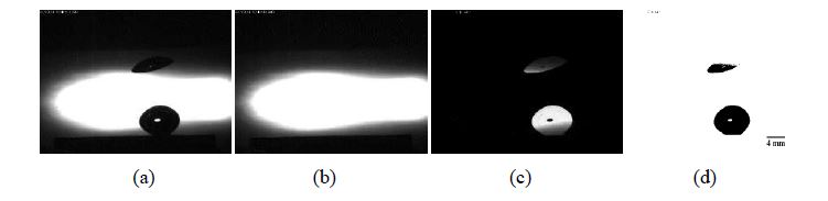
Figure 27 Sequence of image processing (a) Raw image of bubble (b) Background (c) Bubble image after background subtraction (d) Image after threshold applied.
Bubble morphology and detachment diameter
Experiments were conducted on glass bubble absorber with swirl entry of air by varying the operating parameters viz. air flow rate from 0.05 to 0.3 SLPM and water flow rate from 0.5 to 3.5 LPM in flowing water conditions. The bubble formation studies from a submerged orifice are carried out in quiescent water and flowing water conditions. The photographic sequence of air bubbles growing from the swirl generator or nozzle surface in still water for different air flow rates is shown in figure 28. It was observed that the bubbles are formed on the surface of the swirl generator, continuously grow to a maximum volume and detaches from the swirl generator surface and then rise to the top due to buoyancy. The bubble evolution process was divided into three stages: bubble initiation, growth, and detachment. The bubble emerges from the swirl generator surface during the initial stage when the pressure in the compressor storage tank (air line) exceeds the required threshold pressure value, depending on the hydrostatic water level and nozzle. In this stage,the bubble’s shape seems like a segment of a sphere. As the air is continuously fed into the bubble, the bubble volume increases, and this bubble is acted upon by buoyancy, termed the growth stage. But due to the higher constant surface tension force than upward buoyancy force, the bubble still adhered to the nozzle surface. Once this bubble reaches its maximum volume, the buoyancy force acting on its surface overcoming the surface tension force, and it tries to lift the bubble from the swirl generator surface. The instance at which the bubble is about to leave the nozzle surface is called as detachment phase. After this,three stages repeated periodically with a delay between the bubble detachment and initiation stages. The bubbles were nearly spherical at lower gas flow rates due to the dominance of surface tension force.Figure 28.
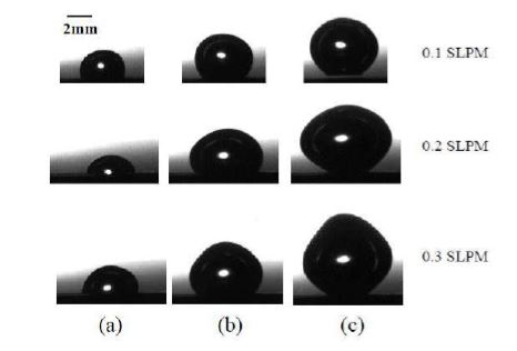
Figure 28. Captured sequence images of air bubbles in still water (a) Bubble initiation (b)Bubble growth (c) Bubble detachment.
The bubble formation phenomenon decides the primitive size of the bubble in the system that governs the interfacial area and mixing characteristics. In order to understand the impact of operating parameters on bubble formation characteristics, non-dimensional numbers are used. Variation of bubble diameter ratio (db ∗ = db do) during the detachment stage in still water is depicted in figure 29. In still water, bubble diameter is mainly decided based on the balance between buoyancy and surface tension force. The bubble volume increases as the Weber number increases because the gas momentum has enough force to push the liquid over the bubble tip. Thus, the detachment diameter increases as the air flow rate increases.
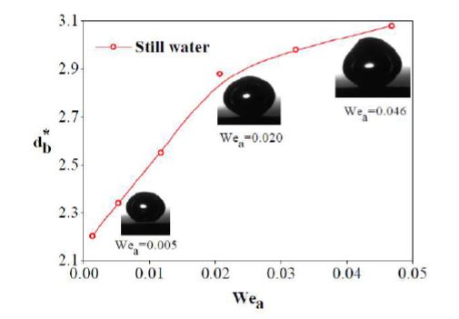
Figure 29. Non-dimensional bubble diameter variation with Weber number of air in still water.
Figure 30 compares the experimental bubble detachment diameter with a correlation that existed in the literature for various gas flow rates in still water. It is observed that the presence of swirl flow resulted in smaller bubble ratios than the absence of swirl flow except at a lower air flow rate Wea of 0.001. This is due to the shearing force imparted by the swirl motion on rotating air, resulting in a smaller bubble generation. The bubble ratio in the present study is 5.15% to 13.24% smaller in the influence of swirl flow than in the without swirl flow.
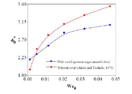
Figure 30. Comparison of non-dimensional bubble diameter with the reported literature data.
The mechanism of bubble formation in flowing water situations is slightly different than that in still water. The water motion significantly impacts bubble characteristics apart from the factors that influence still water. Image sequence of air bubbles in flowing water situations for various water flow rates for a 0.2 SLPM air flow rate is shown in figures 31 and 32. The bubble evolution process was divided into three stages here, as a still water case. This is only qualitative analysis, and quantification aspects will be discussed separately. The forces acting on the bubble are buoyancy, surface tension, inertia. It is observed that the bubbles in flowing situations tend to be hemispherical due to the dominance of inertial forces at lower and higher gas flow rates.
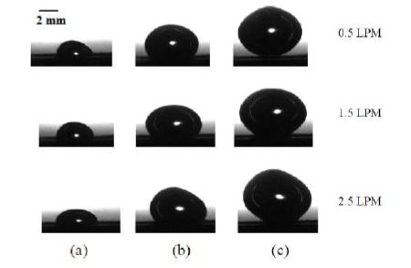
Figure 31. Captured sequence images of air bubbles in co-current water flow at 0.2 SLPM air flow rate (a) Bubble initiation (b) Bubble growth (c) Bubble detachment.
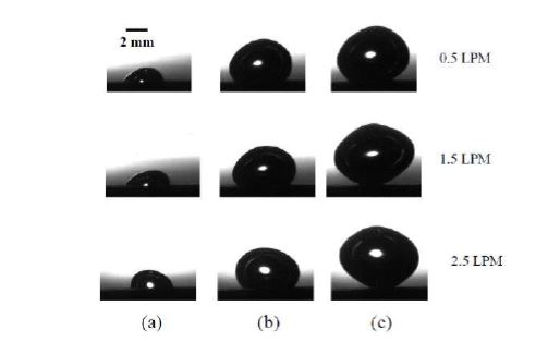
Figure 32. Captured sequence images of air bubbles in countercurrent water flow at 0.2 SLPM air flow rate (a) Bubble initiation (b) Bubble growth (c) Bubble detachment.
The results are quantified in terms of non-dimensional bubble diameter to understand the effect of water flow direction. Figure 33(a) shows the variation of bubble diameter during detachment in co-current water flow situations. This is because the co-current flow of water exerts a pressure force on the bubble surface in an upward direction caused by water inertia.This force will aid buoyancy and lift the bubble from the nozzle surface very early. As a result, the bubble diameter is smaller than in still water. Furthermore, as the water flow rate increases, the drag force acting on the bubble increases, attempting to lift the bubble as soon as possible without increasing bubble volume. As a result, the departure bubble diameter decreases with an increase in water flow rate. It was also observed that in cocurrent water flow, bubble diameter increases as air flow rate increases. Figure 33(b) shows the departure bubble diameter ratio as a function of Weber number in countercurrent water flow direction. Countercurrent water exerts a downward pressure force on the growing bubble, thus delaying the detachment and resulting in a larger bubble diameter than still water. Due to increased downward pressure force, the bubble diameter increases with an increased water flow rate.
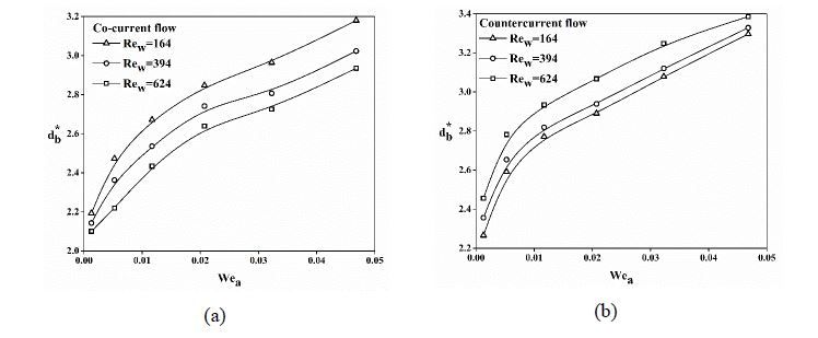
Figure 33. Variation of non-dimensional bubble diameter with water flow rate (a) Co-current water flow (b) Countercurrent water flow.
The effect of water flow direction on bubble detachment diameter is depicted in Figure 34. The diameter of a bubble in co-current flow is smaller than in countercurrent flow, and the diameter of a bubble in countercurrent flow is larger than in still water. It was noticed that by changing the water flow direction and flow rate, the water flowing configurations could help to control the bubble size more effectively than still water. It is well known that smaller bubbles have a higher interfacial area in the bubble absorber, which helps to improve the 28 system performance characteristics. In this point of view, the co-current flow of water in a bubble absorber is recommended to have better heat and mass transfer characteristics.
Conclusions:
- Placing the cavity type swirl generator (0o camber angle and 20o twist angle with 4 nozzles) at the bottom of the glass absorber imparted the swirl motion to air.
- Bubble behaviour was visualised using photographic studies. The bubble tends to be spherical in still water at lower air flow rates, whereas it is hemispherical at higher gas flow rates in still and flowing water.
- Bubble characteristics were significantly influenced by the air flow rate, water flow rate and water flow direction. Bubble size and rise velocity are important controlling parameters for improving the performance of the equipment.
- Bubble diameter ratio during detachment increases with Weber number of air regardless of water flow condition.
- Because co-current water flow direction resulted in a smaller departure bubble diameter than other water flow configurations, it is recommended to use cocurrent flow in bubble absorber to have better performance characteristics.
Visible outcomes:
- N.R. Sanikommu, A. Mani, S. Tiwari, Hydrodynamic air bubble characteristics in a bubble absorber with swirl entry of air in different water flow configurations. (Manuscript communicated to IJTh.Sc.)
- N.R. Sanikommu, A. Mani, S. Tiwari, Bubble dynamics studies in an absorber with swirl entry of an absorption refrigeration system, 18th Int. Refrig. Air Cond. Conf. Purdue, May 24-28. 2393 (2021) 1–9.
1.5. Generator Studies
Objectives:
- To study the generation process of R134a vapour from R134a – DMF solution.
- To develop a numerical model for tubular and compact generators of the absorption refrigeration system.
- To conduct the experiments to evaluate heat and mass transfer characteristics of tubular and compact generator with swirl entry.
- To make comparative heat and mass transfer studies on a tubular and compact generator.
Summary of Work Done:
- A literature survey has been carried out for tubular generators of the absorption refrigeration system.
- Experimental system fabrication has been started and may take couple of months to complete. Then, experiments will be started.
Literature survey:
- Balamurugan and Mani, 2012 carried out detailed experimental and numerical studies on the generator using R134a-DMF. Based on this study, an empirical correlation has been proposed, which can be used for design purpose. Determan and Garimella, 2011 presented the results of the experimental and analytical study of ammonia-water desorption in a microchannel desorber. It was concluded that the microchannel heat and mass transfer technology could be successfully used for both desorption and absorption to package an absorption heat pump system for smallcapacity applications.
- Horuz and Callander, 2004 used a generator of falling film type with horizontal tubes where the heating oil flows inside the tube bank, and ammonia-lithium nitrate solution flows as a falling film on the tube outside, from where ammonia vapour is generated. A numerical model of the horizontal falling film generator was developed that divided the system into three different thermal elements: flow inside the tube, heat conduction in the tube wall and falling film solution flow. The model was tested and validated with experimental data. Agreement between experimental and numerical data for heat flux and temperature profiles in the oil and solution flow was found to be good. 30
- Táboas et al., 2010 used a plate heat exchanger as desorber of absorption refrigeration machine and investigated saturated flow boiling heat transfer and associated frictional pressure drop of ammonia-water flowing in the vertical plate heat exchanger. Results showed that for the selected operating conditions, the boiling heat transfer coefficient was highly dependent on mass flux, whereas the influence of heat flux and pressure were negligible mainly at higher vapour qualities.
- Matsuda et al., 1994 conducted experiments on a generator in a water-lithium bromide absorption refrigerating machine using a vertical falling-film type of stainless steel column. It was found that measured evaporation rate decreased with a decrease in pressure and an increase in the concentration of LiBr in the falling liquid.
References:
- A. Matsuda, K.H. Choi, K. Hada, T. Kawamura, Effect of pressure and concentration on performance of a vertical falling-film type of absorber and generator using lithium bromide aqueous solutions, Int. J. Refrig. 17 (1994) 538–542.
- M. Fatouh, S. Srinivasa Murthy, Performance of an HCFC22-based vapour absorption refrigeration system, Int. J. Refrig. 18 (1995) 465–476.
- I. Dincer, M. Edin, I.E. Ture, Investigation of thermal performance of a solar powered absorption refrigeration system, Energy Convers. Manag. 37 (1996) 51–58.
- P. Balamurugan, A. Mani, Experimental studies on heat and mass transfer in tubular generator for R134a-DMF absorption refrigeration system, Int. J. Therm. Sci. 61 (2012) 118–128.
- M.D. Determan, S. Garimella, Ammonia–water desorption heat and mass transfer in microchannel devices, Int. J. Refrig. 34 (2011) 1197–1208.
- I. Horuz, T.M.S. Callander, Experimental investigation of a vapor absorption refrigeration system, Int. J. Refrig. 27 (2004) 10–16.
- A. Matsuda, K.H. Choi, K. Hada, T. Kawamura, Effect of pressure and concentration on performance of a vertical falling-film type of absorber and generator using lithium bromide aqueous solutions, Int. J. Refrig. 17 (1994) 538–542
- F. Táboas, M. Vallès, M. Bourouis, A. Coronas, Flow boiling heat transfer of ammonia/water mixture in a plate heat exchanger, Int. J. Refrig. 33 (2010) 695–705.
- P. Balamurugan, A. Mani, Comparison of compact and tubular generators performance 31 for R134a–DMF, Exp. Therm. Fluid Sci. 45 (2013) 54–62.
- J. Cerezo, R. Best, J.J. Chan, R.J. Romero, J.I. Hernandez, F. Lara, A Theoretical- Experimental Comparison of an Improved Ammonia-Water Bubble Absorber by Means of a Helical Static Mixer, Energies. 11 (2018).
- J. Cerezo, R. Best, J.J. Chan, R.J. Romero, J.I. Hernandez, F. Lara, A Theoretical- Experimental Comparison of an Improved Ammonia-Water Bubble Absorber by Means of a Helical Static Mixer, Energies. 11 (2018).
Experimental setup:
- Figure 34 show that schematic diagram for the experimental studies on compact generators.
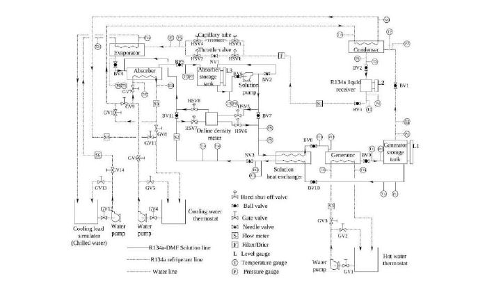
Figure 34. Schematic diagram for the experimental studies on compact generators.
Compact generator dimenstion has been arrived and show in table 1 below.
| Heat exchanger type | Plate type |
|---|---|
| Tube diameter | 12.7 mm |
| Number of plates | 24 |
| Plate height | 25.4 mm |
| Plate breadth | 12 mm |
| Maximum line pressure | 20 bar |
Fabrication of equipment and purchase of heat exchanger is on the process.
- The equipments required for falling film measurement studies using the image processing technique has been purchased. The few equipment has reached the Refrigeration and Air Conditioning (RAC) Laboratory, Department of Mechanical Engineering IIT Madras.
- The list of equipment that has been ordered and its status are listed below:
| Si. No. | Equipment details | Status |
|---|---|---|
| 1. | Online density meter | 1. Reached RAC Lab and demonstration completed. 2. Figure 35 – Photograph of Online density meter. |
| 2. | Mass flow controller | 1.Just now reached RAC Lab. |
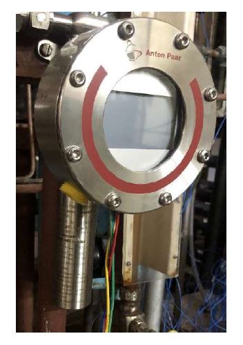
Figure 35. Photograph of Online density meter.
1.6. Vapour Jet Refrigeration System
Objectives:
- To design a primary nozzle (convergent-divergent) built with a profile, which induces high momentum exchange between the primary fluid and the secondary fluid.
- A numerical model will be developed to simulate the ejector.
- To analyze the ejector flow field by Schlieren flow visualization technique.
- Visualization of ejector flow field by Particle Image Velocimetry (PIV) method.
- Flow visualization of entrainment, mixing process, location of both normal & oblique shocks in ejector to be studied.
- To carry out performance analysis of the ejector through experimentation with newer working fluids.
Summary of Work Done:
- A literature survey has been carried out for vapour jet refrigeration system.
- Experimental system fabrication has been started and may take couple of months to complete. Then, experiments will be started.
Literature survey:
- Parveen Banu and Mani, 2019 conducted three-dimensional numeric studies of ejector with swirl generator. They concluded, swirl increases the Entrainment performance due to better momentum exchange between the motive and secondary streams compared to ejector without swirl generator.
- Rao and Jagadeesh, 2014 analyzed two novel supersonic nozzles- Tip Ring Supersonic Nozzle and Elliptic Sharp Triped Shallow Lobed Nozzle have been developed to enhance mixing at high speed. Whe applied to a supersonic ejector, both nozzles achieve a 30% increase in entrainment of secondary flow.
- Rao and Jagadeesh, 2014 investigated inhanced mixing due to flow instabilities by adding lobes to the circular nozzle. It has been seen that pressure recovery was found to increase upto a particular perimeter value and above that frictional losses increases thus reducing pressure recovery further.
- Selvaraju and Mani, 2004 developed computer code on the existing one dimensional ejector theory. The effect of operational parameters and ejector configurations of the system on critical performance are studied. Comparison of performance of the system using environment friendly refrigerant is made such as R134a, R152a, R290, R600a and R717.
- Sun, 1996 investigated the effects of ejector geometries on system performance. Parameters such as boiler, evaporator and condenser temperature are being analyzed to found out the variation of system properties such as Entrainment ration, COP and refrigerating capacity correspondingly they studied the variation in dimensions of nozzle, diffuser and length of the ejector.
- Chang and Chen, 2000 investigated petal nozzle by testing it under various operating conditions such as generator, evaporator and condenser temperature. Testing of ejector for various area ratio (AR) is done. It is being seen that, there is an enhancement in compression ratio and entrainment ratio for a petal with larger area ration.
- Selvaraju and Mani, 2006 did experimental investigation on the performance of a vapour ejector refrigeration system using R134a as working fluid. The influence of generator, evaporator and condenser temperature on the system performance is studied.
- Cizungu et al., 2001 simulated one-dimensional analysis based on mass, momentum and energy balance and validated the same with experimental results from the literature.
- Bouhanguel et al., 2011studied the flow field structure in the ejector mixing using schlieren optical measurements. Two quartz glass windows were installed in the two sides of the mixing chamber to observe shock structures.
- Bouhanguel et al., 2011 and Desevaux et al., 2004 carried out CFD modelling of the ejector to investigate the flow regimes with and without secondary choking and validated the same by comparing the numerical results with laser tomographic images.
- Senthil Kumar et al., 2007 studied flash desalination technology, by which freshwater is produced from seawater by evaporation and subsequent condensation. A two-phase jet pump is designed, developed and tested for such a desalination system to create and maintain vacuum inside the flash chamber. Flow visualisation was made experimentally to find jet dispersion in the jet pump, which facilitates the determination of the optimum length of the mixing tube for the specified inlet conditions for different orifice diameters and different orifice spacing.
- Ruetten and Woldegiorgis, examined the spreading of the vortices and the behavior of the core part. Incompressible laminar flows at low Reynolds numbers are simulated addressing the fundamental physical mechanism of vortex interaction, destructive shearing flows and vortex reorganization and reconnection in the wake field of lobed nozzles. He found the occurrence of the vortex ring like structure in the case of seven twisted lobes preventing efficient mixing.
- Zhang et al., 2017 he investigated experimentally the flow structures and mixing characteristics with the existence of large-scale streamwise vortices generated by a lobed mixer. He stated that the interaction of streamwise and spanwise vortices leads to the breakup of large scale structures, which can promote molecular mixing.
- Yu and Yip, 1997 his study provides detailed velocity information in the mixing region of two stream, mixing flows with streamwise and normal vorticity for the computational fluid dynamics (CFD) methods validation.
- Eames, 2002 they used a method, which assumes a constant rate of momentum exchange within the diffuser passage of a supersonic jet pump. Passage radius for the CRMC diffuser varies in such a way to produce a gradual change in flow area from inlet to outlet. CRMC design produces a gradual decrease in local Mach number, eliminating the shock process which produces a sharp reduction in the conventional design.
- The list of equipment that has been ordered and its status are listed below:
| Si. No. | Equipment details | Status |
|---|---|---|
| 1. | Endoscopy arm along with seeding pump | 1.Purchase order has released. |
References:
- Parveen Banu, J., Mani, A., 2019. Numerical studies on ejector with swirl generator. Int. J. Therm. Sci. 137, 589–600. 36
- Rao, S.M. V, Jagadeesh, G., 2014. Novel supersonic nozzles for mixing enhancement in supersonic ejectors. Appl. Therm. Eng. 71, 62–71.
- S.M. V Rao, G. Jagadeesh, Novel supersonic nozzles for mixing enhancement in supersonic ejectors, Appl. Therm. Eng. 71 (2014) 62–71.
- A. Selvaraju, A. Mani, Analysis of a vapour ejector refrigeration system with environment friendly refrigerants, Int. J. Therm. Sci. 43 (2004) 915–921.
- D.-W. Sun, Variable geometry ejectors and their applications in ejector refrigeration systems, Energy. 21 (1996) 919–929.
- Y.-J. Chang, Y.-M. Chen, Enhancement of a steam-jet refrigerator using a novel application of the petal nozzle, Exp. Therm. Fluid Sci. 22 (2000) 203–211.
- A. Selvaraju, A. Mani, Experimental investigation on R134a vapour ejector refrigeration system, Int. J. Refrig. 29 (2006) 1160–1166.
- K. Cizungu, A. Mani, M. Groll, Performance comparison of vapour jet refrigeration system with environment friendly working fluids, Appl. Therm. Eng. 21 (2001) 585–
- A. Bouhanguel, P. Desevaux, E. Gavignet, Flow visualization in supersonic ejectors using laser tomography techniques, Int. J. Refrig. 34 (2011) 1633–1640.
- P. Desevaux, A. Mellal, Y. Alves de Sousa, Visualization of Secondary Flow Choking Phenomena in a Supersonic Air Ejector, J. Vis. 7 (2004) 249–256.
- A. Bouhanguel, P. Desevaux, E. Gavignet, Flow visualization in supersonic ejectors using laser tomography techniques, Int. J. Refrig. 34 (2011) 1633–1640.
- R. Senthil Kumar, S. Kumaraswamy, A. Mani, Experimental investigations on a twophase jet pump used in desalination systems, Desalination. 204 (2007) 437–447.
- M. Ruetten, F. Woldegiorgis, Vortical Flow Structure Genesis of Lobed Nozzle Flows, in: 46th AIAA Fluid Dyn. Conf.
- D. Zhang, J. Tan, J. Hou, Structural and mixing characteristics influenced by streamwise vortices in supersonic flow, Appl. Phys. Lett. 110 (2017) 124101.
- S.C.M. Yu, T.H. Yip, Experimental investigation of two-stream mixing flows with streamwise and normal vorticity, Int. J. Heat Fluid Flow. 18 (1997) 253–261.
- I.W. Eames, A new prescription for the design of supersonic jet-pumps: the constant rate of momentum change method, Appl. Therm. Eng. 22 (2002) 121–131.
One-dimensional analysis:
Ejector geometry working with R134a was arrived by solving the conservation equations of mass, momentum and energy using MATLAB. Also efficiencies of nozzle, mixing tube, diffuser and frictional losses were included in the coding. Basic geometry arrived from one-dimensional analysis was shown in Figure 36.
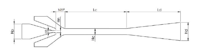
Figure 36. Geometric details of ejector obtained from one-dimensional analysis.
One-dimensional analysis was used to study the parametric studies of ejector under various simulated operating conditions. Effect of generator temperature on the critical entrainment ratio and Coefficient of performance (COP) was shown in Figure 37. The entrainment ratio and COP increases with increase in generator temperature. Figure 38 shows the effect of condenser temperature on the critical entrainment ratio. Increase in condenser temperature, causes decrease in entrainment ratio. Increase in evaporator temperature causes increase in entrainment ratio, as shown in Figure 39.
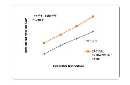
Figure 37. Effect of generator temperature on the critical entrainment ratio and COP.
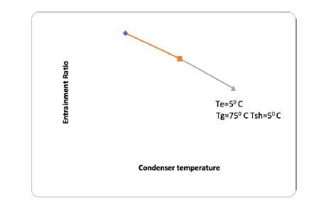
Figure 38. Effect of condenser temperature on critical entrainment ratio.
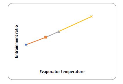
Figure 39. Effect of evaporator temperature on critical entrainment ratio.
Two-dimensional analysis:
In this study, the performance of VJRS ejectors with R134a have been investigated numerically treating 2D flow its axis symmetric condition using commercial CFD software. For the numerical simulations on the selected ejector, generator temperature is varied from 55oC to 80oC, the condenser temperature is varied from 20oC to 45oC, and the evaporator temperature is varied from -10oC to 10oC. Numerical results obtained contribute to understanding the local structure of the flow. Moreover, the results help in identifying the optimum operating condition for each value of ejector area ratio. Flow in the ejector of VJRS is typically compressible and turbulent. Present study employs realizable k-ε turbulence model to describe the turbulent behavior in the ejector. Density-based implicit solver is used to solve nonlinear governing equations. In addition, focus has been on the 2-D axis symmetric steady flow analysis. Mesh consists of triangular Entrainment ratio Evaporator temperature elements everywhere except near the wall of the constant area mixing chamber and the convergent divergent nozzle where quadrilateral elements are used. The grid has been refined in the region where the primary and the secondary flows interact. Adaptive mesh size is selected with respect to the change in operating condition. Moreover, systematic grid convergence studies have been performed to optimize the mesh size. Influence of generator, evaporator and condenser temperatures on the system performance is studied numerically for three different area ratios. Present study suggests that the entrainment ratio decreases as the generator temperature increases for each area ratio. Higher entrainment ratio can be achieved by increasing the evaporator temperature.But higher evaporator pressure causes formation of oblique shock at the exit of the convergent-divergent nozzle. Lower evaporator pressure leads to expansion waves at the exit of convergent-divergent nozzle. So, evaporator temperature has significant role in designing and operation of a supersonic ejector. A higher value of area ratio corresponds to higher entrainment ratio for all the operating conditions. It is further observed that lower area ratios are able to achieve higher critical condenser temperatures. Figure 40 shows the effect of evaporator temperature on supersonic jet.
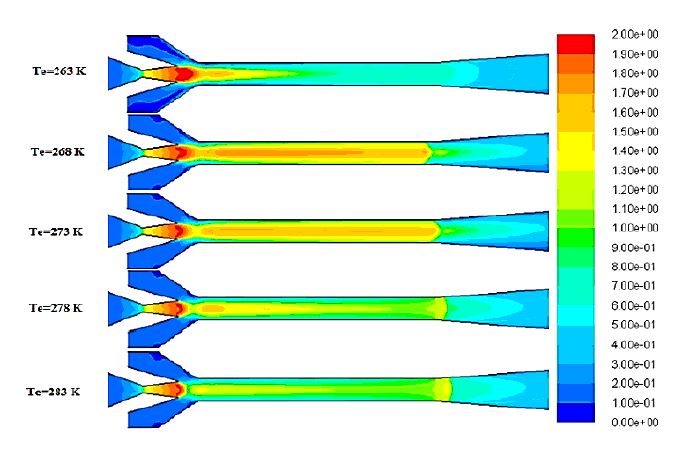
Figure 40. shows the effect of evaporator temperature on supersonic jet.
PIV experimental study setup for ejector:
- Initial, PIV experimental setup for ejector has been designed using 3D modleing software. Ejector 3D model is shown in figure 41.
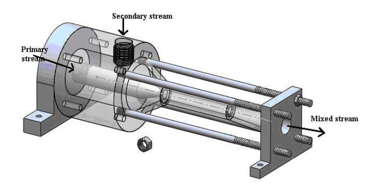
Figure 41. Ejector 3D modle.
- Fabrication of ejector for PIV studies is going on.
Collaborations
Societal impact
Solar Desalination System
Higher heat transfer with modified heat exchanger tube will reduce the energy requirement. For Multi-Effect Desalination (MED) plants, which depend on heat source of fossil fuel origin, the decrease in energy requirement can reduce the carbon footprint. The improved design of conventional desalination system with integration of solar energy will have effective fresh water production rate. The integration of solar energy with desalination system and compacting the system will be more useful for people where access to fresh water is limited. Also, this type of desalination can produce water even at industrial water quality.
Solar Cold Storage
According to the Ministry of Food Processing Industry, Government of India [2010], wastage Rs.926.51 billion every year, due to the country’s lack of adequate cold storage facilities and refrigerated transport. Hence, to mitigate wastage of fruits, vegetables, food products including marine and poultry, development of solar cold storage will address the above in addition to the energy and environmental issues in National and International scenario. In India, solar energy is available abundantly. This freely distributed available solar energy can be utilized effectively to build cold storage. With this system, there won’t be any depletion of non-renewable energies, and the reduction of carbon content in the atmosphere is possible with the help of solar power. Also, the compacted system can be easily installed at any part of the country with less space and good performance characteristics.
Sustenance statement :
Solar Desalination System
The measuring instrument and equipment, purchased under IoE grant, will be handled by local laboratory staff and research scholars. This instrument can be used for new upcoming scholars. Maintenance of the instrument will be met out from the revenue generated from the start-up established in IITM Research Park based on the current proposal.
Solar Cold Storage
The measuring instruments and equipment, purchased under IoE grant, will be handle by local laboratory staff for the usage of research scholars. These instruments can be used for new upcoming scholars. Maintenance of the instrument will be met out from the revenue generated from the start-up established based on the current proposal. Based on these studies, a new industry will be developed in this area after 5 years. Due to solar Vapour Absorption Refrigeration System (VARS) and Vapour Jet Refrigeration System (VJRS) cold storage system, the wastage of agricultural produce will reduce, and marketing of these goods will increase. In turn, this system will help to increase the country’s economy and GDP.
Technical/ Scientific Progress
New work done in the project
- Falling film measurement studies :
- The equipment required for falling film measurement studies has been purchased. Most of the equipment has reached the RAC Laboratory. Few equipment like high speed infra red camera, ultrasonic transducer needs to reach the Lab. Mirrors and other accessories need to re-float the tender.
- The experimental setup for falling film measurement technique studies using image processing has been fabricated and installed at RAC Laboratory, Department of Mechanical Engineering IIT Madras. Initial trials have been started using high speed camera to measure the falling film thickness over the horizontal tube (plane tube).
- Falling film heat transfer studies using non-contact type ultrosonic sensor on copper foam rapped tube have been completed. It is observed that foamed tube enhances the heat transfer rate by 2.72 times that of copper bare tube and mass transfer rate by 2.3 times.
- Falling film heat transfer studies using laser interferometric method shows that the improvement in heat and mass transfer is similar.
- Development of Solar Vapour Absorption Refrigeration Cold Storage :
- The swirl generator (SG) design is carried out using numerical simulations to impart rotary motion to the bubbles in a bubble absorber. The SG consists of four nozzles with a profile of 0o camber angle and 20o twist angle. This SG is fabricated with Fusion Deposition Modelling (FDM) type 3-dimensional (3D) printing method with Acrylonitrile Butadiene Styrene (ABS) material. Fabricated swirl generator is installed at the bottom of the absorber in the vapour stream in the copper pipe. Installation of SG altered the trajectory of the bubbles and the residence time of the bubbles. This will improve bubble absorber’s heat and mass transfer characteristics.
- Preliminary visualization experiments are carried out with air and water. The effect of the SG on bubble detachment diameter. It can be seen that the bubble ratio (ratio of bubble diameter to nozzle diameter) in the present study is 5.15% to 13.24% smaller in the influence of swirl flow than in the without swirl flow. The experiments are carried out in still and flowing water situations. The effect of the operating parameters on hydrodynamic bubble characteristics is determined. Finally, the empirical correlations are developed for bubble diameter during detachment. The visualization studies will be extend to refrigerant-absorbent pairs in future.
- Development of Solar Vapour ejector refrigeration system :
- Literature work on the vapour jet refrigeration system is being carried out. Based on the literature survey, the optimal profile of the primary nozzle will be selected by using CFD studies. This will help understand the rise in momentum transfer between two fluids.
Infrastructure developments
- Falling film measurement studies :
- We have developed falling film measurement studies experimental test rig using sophisticated equipment to capture film at high speed using high speed camera.
- Development of Vapour Absorption Refrigeration Cold Storage :
- In this project, a mass flow measuring device called mass flow meter is used to measure the air flow rate accurately. Glass and copper absorbers are fabricated for visualization of refrigerant bubbles and to study the heat and mass transfer studies. An accurate density meter is bought to measure the density of R134a-DMF solution during the experiments online.
- Development of Vapour ejector refrigeration system :
- Laser equipment and vibration isolation table are ready in RAC Lab for PIV experimental studies.
- Endoscopy arm is on its way to reach RAC lab.
Output
- Falling film measurement studies :
- Jayakumar, A., Balachandran, A., Mani, A., Balasubramaniam, K., 2019. Falling film thickness measurement using air-coupled ultrasonic transducer. Exp. Therm. Fluid Sci. 109, 109906.
- Maliackal, A.K., Ganesan, A.R., Mani, A., 2021. Interferometric analysis of flow around a horizontal tube falling film evaporator for MED systems. Int. J. Therm. Sci. 161, 106745.
- Arjun, J., Mani, A., 2021. Experimental and Numerical Study of Hydrodynamic and Heat Transfer Characteristics of Falling Film Over Metal Foam Layered Horizontal Tube. J. Heat Transfer.
- Maliackal, A.K., Ganesan, A.R., Mani, A., 2021. Interferometric analysis of flow around a horizontal tube falling film evaporator for MED systems. Int. J. Therm. Sci. 161, 106745.
- Development of Vapour Absorption Refrigeration Cold Storage :
- N.R. Sanikommu, A. Mani, S. Tiwari, Hydrodynamic air bubble characteristics in a bubble absorber with swirl entry of air in different water flow configurations. (Manuscript under revision).
- N.R. Sanikommu, A. Mani, S. Tiwari, Bubble dynamics studies in an absorber with swirl entry of an absorption refrigeration system, 18th Int. Refrig. Air Cond. Conf. Purdue, May 24-28. 2393 (2021) 1–9.
Review papers
I. PAVITHRAN, V. R. UNNI AND R. I. SUJITH (2021) Critical transitions and their early warning systems in thermoacoustic systems, Invited Review, The European Physical Journal Special Topics, link
Sujith, R. I. & V. R. Unni (2021) “Dynamical systems and complex systems theory to study unsteady combustion”, Invited Topical Review, Proceedings of the Combustion Institute link
Sujith, R. I., & Unni, V. R. (2020). Complex system approach to investigate and mitigate thermoacoustic instability in turbulent combustors. Physics of Fluids, 32(6), 061401 link
Juniper, M. P., & Sujith, R. I. (2018) Sensitivity and nonlinearity of thermoacoustic oscillations. Annual Review of Fluid Mechanics, 50, 661-689 link
Publications with international collaborators
Dhadphale, J. M., Unni, V. R., Saha, A., & Sujith, R. I. (2022). Neural ODE to model and prognose thermoacoustic instability. Chaos: An Interdisciplinary Journal of Nonlinear Science, 32(1), 013131. link
Bury, T. M., Sujith, R. I., Pavithran, I., Scheffer, M., Lenton, T. M., Anand, M., & Bauch, C. T. (2021). Deep learning for early warning signals of tipping points. Proceedings of the National Academy of Sciences, 118(39). link
Bedard, M. J., Gejji, R. M., Anderson, W. E., Austin Jr, B. L., Kasthuri, P., & Sujith, R. I. (2021). Detailed Measurement of Oxidizer-Rich Staged Combustion Injector Dynamics in Model Rocket Combustors. AIAA Journal, 1-16. link
Ruiz, E. A., Unni, V. R., Pavithran, I., Sujith, R. I., & Saha, A. (2021). Convolutional neural networks to predict the onset of oscillatory instabilities in turbulent systems. Chaos: An Interdisciplinary Journal of Nonlinear Science, 31(9), 093131. link
Varghese, A. J., Chechkin, A., Metzler, R., & Sujith, R. I. (2021). Capturing multifractality of pressure fluctuations in thermoacoustic systems using fractional-order derivatives. Chaos: An Interdisciplinary Journal of Nonlinear Science, 31(3), 033108.link
Roy, A., Singh, S., Nair, A., Chaudhuri, S., & Sujith, R. I. (2021). Flame dynamics during intermittency and secondary bifurcation to longitudinal thermoacoustic instability in a swirl-stabilized annular combustor. Proceedings of the Combustion Institute, 38(4), 6221-6230. link
Singh, S., Roy, A., K.V, Reeja, Nair, A., Chaudhuri, S., & Sujith, R. I. (2021). Intermittency, Secondary Bifurcation and Mixed-Mode Oscillations in a Swirl-Stabilized Annular Combustor: Experiments and Modeling. Journal of Engineering for Gas Turbines and Power, 143(5), 051028.link
Braun, T., Unni, V. R., Sujith, R. I., Kurths, J., & Marwan, N. (2021). Detection of dynamical regime transitions with lacunarity as a multiscale recurrence quantification measure. Nonlinear Dynamics, 1-19.link
Krishnan, A., Sujith, R. I., Marwan, N., & Kurths, J. (2021). Suppression of thermoacoustic instability by targeting the hubs of the turbulent networks in a bluff body stabilized combustor. Journal of Fluid Mechanics, 916. link
Kushwaha, A., Kasthuri, P., Pawar, S. A., Sujith, R. I., Chterev, I., & Boxx, I. (2021). Dynamical characterization of thermoacoustic oscillations in a hydrogen-enriched partially premixed swirl-stabilized methane/air combustor. Journal of Engineering for Gas Turbines and Power, 143(12). link
Pavithran, I., Unni, V. R., Saha, A., Varghese, A. J., Sujith, R. I., Marwan, N., & Kurths, J. (2021). Predicting the Amplitude of Thermoacoustic Instability Using Universal Scaling Behavior. Journal of Engineering for Gas Turbines and Power, 143(12). link
Publications from purely IIT Madras effort
- Tandon, S., & Sujith, R. I. (2021). Condensation in the phase space and network topology during the transition from chaos to order in turbulent thermoacoustic systems. Chaos: An Interdisciplinary Journal of Nonlinear Science, 31(4), 043126. link
- Sahay, A., Roy, A., Pawar, S. A., & Sujith, R. I. (2021). Dynamics of Coupled Thermoacoustic Oscillators Under Asymmetric Forcing. Physical Review Applied, 15(4), 044011. link
- Manoj, K., Pawar, S. A., & Sujith, R. I. (2021). Experimental investigation on the susceptibility of minimal networks to a change in topology and number of oscillators. Physical Review E, 103(2), 022207. link
- Premraj, D., Manoj, K., Pawar, S. A., & Sujith, R. I. (2021). Effect of amplitude and frequency of limit-cycle oscillators on their coupled and forced dynamics. Nonlinear Dynamics, 103(2), 1439-1452. link
- Roy, A., Premchand, C. P., Raghunathan, M., Krishnan, A., Nair, V., & Sujith, R. I. (2021). Critical region in the spatiotemporal dynamics of a turbulent thermoacoustic system and smart passive control. Combustion and Flame, 226, 274-284. link
- Roy, A., & Sujith, R. I. (2021). Fractal dimension of premixed flames in intermittent turbulence. Combustion and Flame, 226, 412-418.link
- Pavithran, I., & Sujith, R. I. (2021). Effect of rate of change of parameter on early warning signals for critical transition. Chaos: An Interdisciplinary Journal of Nonlinear Science, 31(1), 013116. link
- Pawar, S. A., Raghunathan, M., Reeja, K. V., Midhun, P. R., & Sujith, R. I. (2021). Effect of preheating of the reactants on the transition to thermoacoustic instability in a bluff-body stabilized dump combustor. Proceedings of the Combustion Institute, 38(4), 6193-6201. link
- Premraj, D., Suresh, K., Pawar, S. A., Kabiraj, L., Prasad, A., & Sujith, R. I. (2021). Dragon-king extreme events as precursors for catastrophic transition. EPL (Europhysics Letters), 134(3), 34006. link Preprints in arXiv
- Praveen Kasthuri, Pawar, S. A., Rohan Gejji, William Anderson and Sujith, R. I., “Coupled interaction between acoustics and unsteady flame dynamics during the transition to thermoacoustic instability in a multi-element rocket combustor”. link
- Samarjeet Singh, Ankit Kumar Dutta, Jayesh M. Dhadphale, Amitesh Roy, Swetaprovo Chaudhuri, and Sujith, R. I., “Mean-field synchronization model for open-loop, swirl controlled thermoacoustic system”. link
- Sneha Srikanth, Ankit Sahay, Samadhan A. Pawar, Krishna Manoj, Sujith, R. I., “Self-coupling: An Effective Method to Mitigate Thermoacoustic Instability”.link
- Sneha Srikanth, Samadhan A Pawar, Krishna Manoj, and Sujith, R. I., “Dynamical States and Bifurcations in Coupled Thermoacoustic Oscillators”.link
- Induja Pavithran and Sujith, R. I., “Extreme COVID-19 waves reveal hyperexponential growth and finite-time singularity”.link
- Raghunathan Manikandan, Nitin Babu George, Vishnu Unni R, Sujith, R. I., Jürgen Kurths, and Elena Surovyatkina, “Seeds of phase transition to thermoacoustic instability”.link
- Kai Hauke Kraemer, Maximilian Gelbrecht, Induja Pavithran, Sujith, R. I., and Norbert Marwan “Optimal State Space Reconstruction via Monte Carlo Decision Tree Search ”.link
- Ankit Shay, Abhishek Kushwaha, Pawar, S. A., Midhun, P. R, J. Dhadphale, and Sujith, R. I., “Mitigation of thermoacoustic instability in a turbulent combuster via self-coupling”. link
- Shri Vignesh K, Shruti Tandon, Praveen Kasthuri, and Sujith, R. I., “Cluster formation in particle-laden flows is a continuous phase transition”.link
- Manikandan Raghunathan, Nitin Babu George, Vishnu R Unni, Jürgen Kurths, Elena Surovyatkina, Sujith, R. I., “Control of growth of local heat release rate fluctuations to suppress thermoacoustic instability”. link
Conferences
- S. Srikanth, S. A. Pawar, K. Manoj & Sujith, R. I. (2021). “Suppression of Thermoacoustic Oscillations Through Self-Coupling”. Conference on Complex Systems 2021, 25th to 29th October 2021, France, (Online Conference).
- S. Srikanth, S. A. Pawar, K. Manoj & Sujith, R. I. (2021). “Modelling Coupled Thermoacoustic Systems: Synchronization and Amplitude Death”. 74th Annual Meeting of the APS Division of Fluid Dynamics, 21st to 23rd November 2021, USA.
- Sujith, R. I. & V. R. Unni (2021) Dynamical systems and complex systems theory to study unsteady combustion, Invited Topical Review, 38th International Symposium on Combustion, Adelaide, Australia, January 24-29 (Online Conference).
- Sujith, R. I. (2021) Rate dependent transitions in a thermoacoustic system, Conference on Nonlinear Systems and Dynamics (CNSD), 17-22 December (online conference).
- A. Roy, S. Singh, K. V. Reeja, A. Nair, S. Chaudhury and Sujith, R. I. (2021) “Flame dynamics during intermittency and secondary bifurcation to longitudinal thermoacoustic instability in a swirl-stabilized annular combustor”, 38th International Symposium on combustion, Adelaide, Australia, January 24-29 (Online Conference).
- S. A. Pawar, R. Raghunathan, K. V. Reeja, P. R. Midhun and Sujith, R. I. (2021) “Effect of preheating on the transition to thermoacoustic instability in a bluff-body combustor”, 38th International Symposium on combustion, Adelaide, Australia, January 24-29 (Online Conference).
- A. Kushwaha, P. Kasthuri, S. A. Pawar, Sujith, R. I., I. Chterev and I. Boxx (2021) “Dynamical Characterization of Thermoacoustic Oscillations in a Hydrogen-Enriched Partially Premixed Swirl-Stabilized Methane/air Combustor”, ASME Turbo Expo, GT2021-60011(online conference).
- I. Pavithran, V. R. Unni, A. Sahay, A. J. Varghese, Sujith, R. I., N. Marwan and J. Kurths (2021), “Predicting the Amplitude of Thermoacoustic Instability Using Universal Scaling Behaviour”, ASME Turbo Expo, GT2021-60074(online conference).
- A. Sahay, A. Roy, S. A. Pawar and Sujith, R. I. (2021) “Coupled behavior of oscillators under asymmetric forcing”, Dynamics Days Europe, Aug 23-27 (online conference).
- S. Singh, A. Roy, S. Chaudhuri and R.I. Sujith (2021) “Change of criticality in a turbulent annular combustor”, Dynamics Days Europe, Aug 23-27 (online conference).
- S. Srikanth, A. Sahay, S. A. Pawar, K. MANOJ, and Sujith, R. I. (2021) Oscillation quenching through self-coupling: Experiments and Modeling, Conference on Nonlinear Systems and Dynamics (CNSD), 17-22 December (online conference).
- I. Pavithran, V. R. Unni, Sujith, R. I., J. Kurths and N. Marwan (2021), “Recurrence condensation during critical transitions in complex systems”, 9th International Symposium on Recurrence Plots, 22-24 September (online conference).
Invited Talks and Keynote Address
- Complex system approach to investigate & mitigate thermoacoustic instability in turbulent combustors, International Webinar Series on Combustion, June 5, 2021
- Suppression of thermoacoustic instability by targeting the hubs of the turbulent networks in a bluff body stabilized combustor, Network Science for Fluid Mechanics Seminar Series, Dec 3, 2021.
- Condensation in the phase space and network topology during transition from chaos to order in turbulent thermoacoustic systems, Network Science for Fluid Mechanics Seminar Series, Sep 10, 2021.
- R. I. Sujith “Spatiotemporal Dynamics of Thermoacoustic Instability”, International Indo-US online workshop on Application of Machine Learning and Dynamical Systems Approach for Early Detection and Control of Combustion Instabilities on January 5 - 7, 2021
- “Dynamical systems and complex systems theory to study unsteady combustion”, Invited Topical Review, International Symposium on Combustion, Adelaide 2021 January 25-29.
- R. I. Sujith “Complex system approach to investigate and mitigate thermoacoustic instability in turbulent combustors”, Georgia Tech Combustion Webinar, June 5, 2021.
Book Publication
- R. I. Sujith & S. A. Pawar (2021) Thermoacoustic Instability: A Complex Systems Perspective, ISBN: 978-3-030-81134-1, Springer Series in Synergetics.
Patents
Jointly with Potsdam Institute of Climate Impact Research, Germany
- Unni, V. R, Sujith, R. I., Krishnan, A., Marwan, N., and Kurths, J., System and methods for optimizing passive control of oscillatory instabilities in turbulent flows, priority date” February 27, 2018, US Patent number US 10,895,382 B2; accepted for grant & awaiting grant in Europe.
Featured Tutorials
Annual Review of Fluid Mechanics – Tools from Nonlinear Dynamics
International Webinars Organized
We established an international webinar series on Critical Transitions in Complex Systems, with internationally acclaimed speakers. The following webinars have already been conducted:
- Exploring Predictability of Extreme Climate Events via a Complex Network Approach by Prof. Jürgen Kurths, PIK Germany, September 27, 2021.
- Data Analysis on Critical Transitions in Complex Systems and its Application to Early Precision Medicine, Prof. Kazuyuki Aihara, U. Tokyo, October 25, 2021
- Prediction of Chaotic Dynamical Systems using Machine Learning Upcoming talks, Prof. Edward Ott, U. Maryland, November 29, 2021
- Machine Learning for Scientific Discovery, with Examples in Fluid Mechanics, Prof. Steven Brunton, U. Washington, January 31, 2022
The following webinars are planned for the near future:
- Nonlinear dynamics of solid-state systems, Dr. Louis Pecora, NRL Washington, February 28, 2022
- Self-organization in physical and physicochemical systems, Prof. Katharina Krischer, TU Munich, March 28, 2022.
- Studies on the theory of nonlinear dynamics and Murali—Lakshmanan-Chua (MLC) Circuit, Prof. M. Lakshmanan, Bharathidasan U., April 25, 2022.
- Spreading dynamics, self-organization, and stability in complex networks: From neural networks to COVID-19, Dr. Viola Priesemann, MPIDS Göttingen, May 30, 2022.
Media Outreach
- Our work on the effect of rate of change of parameter on early warning signals for critical transitions was a featured article in Chaos: An Interdisciplinary Journal of Nonlinear Science and also appeared in the Scilight collection of American Institute of Physics, January 2021.
- IIT Madras: candle flame oscillators shine light on combustor stability, The Hindu February 08, 2020 Using stacks of candles tied together, and studying pairs, and quartets, of such candles, Dr. Sujith and his team has come up with interesting inputs that will help in building combustors in rockets. The research has been published in reputed journals Scientific Reports and Physical Review E. link
- Research by IIT Madras is among the top papers cited by Chief Advisor to UK PM, The Times of India January 9, 2020 .A research paper by Prof. Sujith and his team was among the papers cited by Dominic Cummings, chief special adviser to the UK Prime Minister, Boris Johnson, to revamp decision-making strategies. Published in Scientific Reports by Nature, the research paper titled “Early warning signals for critical transitions in a thermoacoustic system” looks at early warning systems in physics that could be applied to other areas like finance to epidemics.link
a. Interview in Nature on this news: link
- This IIT-Madras team has a way to kill the hum in gas engines, The Hindu BusinessLine November 26, 2019 Globally, the gas turbine industry loses as much as $1 billion annually due to downtime for turbine inspection and replacement of damaged parts due to such thermo-acoustic oscillations which occur in the combustors. A team led by Prof. Sujith came up with a simple and cost-effective solution for quenching thermoacoustic oscillations developed in multiple combustion systems, where the knowledge for the control of such oscillations remains limited. The research has been published in Chaos journal. link
- IIT-M and GE tie up for precursor technology, The Times of India February 9, 2019 IIT Madras and General Electric (GE) are collaborating on the development of “precursor technology”, where early signal systems warning of engine malfunctions will be developed and applied in real-world situations in GE’s gas turbine component testing facility. According to Prof. Sujith, with its early warning feature, the technology can help GE save substantial money and time in testing their components. link
- Decoding flame behaviour and how it helps jet engine design, The Economic Times March 3, 2019 link
- Brennende Fragen zu singenden Flammen (Burning questions about singing flames) An article about Prof. Sujith’s research from a German research magazine TUM Campus: link
- Emergence of order from chaos in turbulent systems and Bose-Einstein condensation, The Hindu, 5th June 2021. In a combination of theory and experiment, Prof. Sujith and his student Shruti Tandon have come up with an understanding of the emergence of order in chaotic systems by drawing an analogy with a phenomenon widely studied in quantum statistical physics – Bose-Einstein condensation (BEC). The research has been published in the reputed journal Chaos. link
- Smothering the flames of instability, IIT Madras Shaastra May-June 2021. Combustion instability affects gas turbines and jets and rocket engines, and Sujith’s team work used a complex network approach to address it. link
Mobility
Visits planned for PI, co-PIs, international collaborators and students (both inbound and outbound)
International Colloborators visit to IITMadras
Prof.Yann Bartiscoweiz ,UCL, Brussels. Planned to visit IITMadras during August and September 2022. Dean, Global Engagement has approved the proposed visit and other formalities are on anvil.
Dr.Stefan Elbel, UIUC,USA. Planned to visit IITMadras during August 2022. Dean, Global Engagement has approved the proposed visit and other formalities are on anvil.
Mr. Narashimha Reddy Sanikommu, Ph.D. Scholar. Planned to attend PURDUE 2022, USA 19th International Refrigeration and Air-Conditioning Conference during July 2022. He is planning to visit Department of Mechanical Science and Engineering, UIUC,USA after the conference. Process of obtaing permission is on.
Prof.Mani,A. Proposed visit to UIUC,USA and UoM of Minnesota,USA have been taken the approval from Dean,GE. Other formalities to be initiated.
Relationship
Industrial Engagement
- Falling film measurement studies :
- M/s Koushic Pressure Vessels Private Limited, Chennai will be collaborating for the fabrication and improvement in the conventional desalination system. Based on the outcome of different measuring techniques, the improvement will be implemented in the compact desalination system during the Phase – II.
- Development of Solar Vapour Absorption Refrigeration Cold Storage :
- M/s Koushic Pressure Vessels Private Limited, Chennai will be collaborating for fabrication and improvement in the Solar vapour absorption refrigeration cold storage.
- Development of compact solar vapour ejector refrigeration system :
- M/S KCP Solar Pvt. Ltd, Salem, Tamil Nadu will help in the establishment of a photovoltaic power plant system during phase II.
University Engagement
Visits of visiting faculty fellow from UIUC,USA and UCL, Brussels planned to IITM. Visits of Research scholar and PI is planned to UIUC, USA.
Updates
Relevant Updates
Visits of visiting faculty fellows, PI and RS will depend upon COVID19 situation in India, USA and Belgium.
Other relevant updates
- Part of EU project POLKA (Pollution Know-How and Abatement).
- Proposal on “Network Structure of Transitions in Thermo-fluid Systems in Nature & Engineering” is accepted technically by the Office of Naval Research Global, and undergoing the administrative processing.
- Prof. R. I. Sujith was awarded the Distinguished Fellowship of the International Institute of Acoustics and Vibration (2021); Only Indian to be conferred this distinguished fellowship to date.
- Dr. Samadhan A Pawar, Post Doctoral Researcher, won the INAE Young Engineer Award from the Indian National Academy of Engineering for excellence in engineering research.
- Shruti Tandon, DD Student is awarded the Innovative Student Projects Award by the Indian National Academy of Engineering.
- Shruti Tandon, DD Student is awarded Prof. S. L Soni Best M.tech Thesis award-2022 conferred by the International Society for Energy, Environment and Sustainability.
- Krishna Manoj, DD student is awarded the Innovative Student Projects Award by the Indian National Academy of Engineering.